Mask plate assembly and evaporation equipment

A mask and component technology, applied in vacuum evaporation plating, sputtering plating, ion implantation plating, etc., can solve the problems of edge color mixing, top damage to fine metal masks, etc., to reduce the probability of wrinkles, Avoid edge color mixing and improve the effect of support

Active Publication Date: 2021-06-29
BOE TECH GRP CO LTD +1
View PDF10 Cites 1 Cited by
  • Summary
  • Abstract
  • Description
  • Claims
  • Application Information

AI Technical Summary

Problems solved by technology

[0006] When the folds generated by the shielding metal mask are large, it may damage the fine metal mask and cause color mixing at the edge

Method used


Image

  • Mask plate assembly and evaporation equipment
  • Mask plate assembly and evaporation equipment
  • Mask plate assembly and evaporation equipment

Examples


Embodiment 1

[0051] Please combine Figure 7 to Figure 13 It should be understood that this embodiment provides a mask assembly 1 . It includes: a frame 10, a first mask plate 20 and a second mask plate 30 stacked on the frame 10, the first mask plate 20 is located away from the frame from the second mask plate 30 10 on one side.

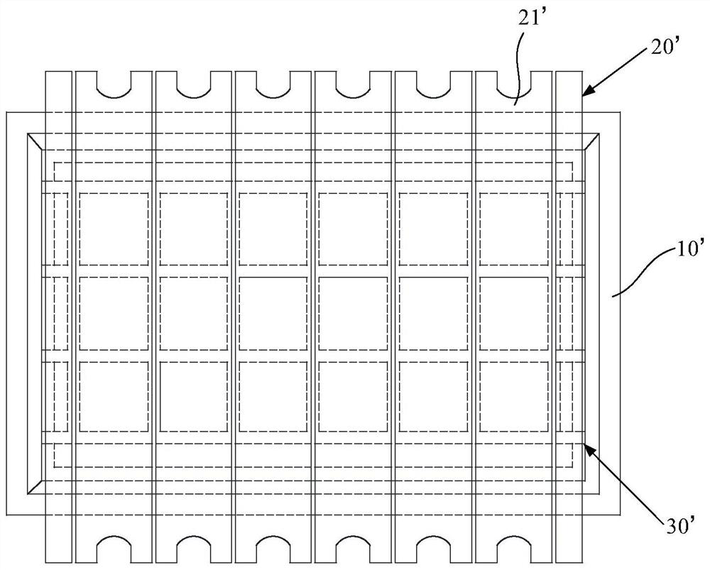
[0052] The first mask plate 20 includes a plurality of mask strips 21 arranged along the first direction, a gap 22 is provided between two adjacent mask strips 21, and each mask strip 21 is provided with a There are a plurality of pixel openings 311 arranged in an array. That is, the first mask 20 is a fine metal mask.

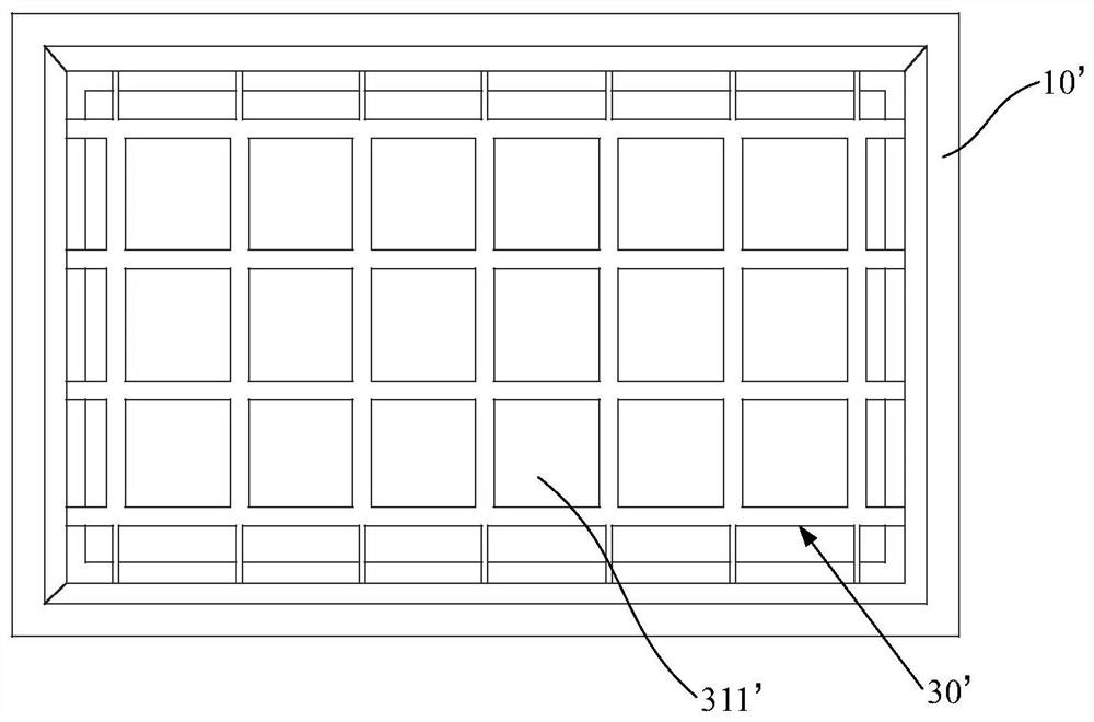
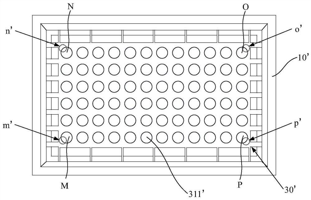
[0053] The second mask plate 30 includes a main body 31 and a support bar arranged along the outer periphery of the main body 31, the first end of the support bar is connected to the main body 31, and the first end of the support bar is the The portion of the support bar that does not coincide with the orthographic projection of the frame 10...

Embodiment 2

[0071] Such as Figure 14 to Figure 19 As shown, the overall structure of the mask assembly of this embodiment is basically the same as the structure in Embodiment 1. The structure of the mask assembly of this embodiment is based on the structure of Embodiment 1, and the rest of the first support The width of the first end 321 of the bar 32 also gradually increases from the direction away from the main body 31 to the direction close to the main body 31 . That is, not only the first support bar 32 located on the outermost side, but also the widths of the first ends 321 of the rest of the first support bars 32 gradually increase from the direction away from the main body 31 to the direction close to the main body 31, That is, the widths of the first ends 321 of all the first support bars 32 gradually increase from a direction away from the main body 31 to close to the main body 31 . In order to further improve the supporting strength of the first supporting bar 32 to the main b...

Embodiment 3

[0081] Such as Figure 20 and Figure 21 As shown, the overall structure of the mask assembly 1 of this embodiment is basically the same as that in Embodiment 2, the difference is that, on the basis of the structure of Embodiment 2, the rest of the second support bars 33 The width of the first end 331 also gradually increases from the direction away from the main body 31 to close to the main body 31 . That is, not only the outermost second support bar 33, but also the widths of the first ends 331 of the other second support bars 33 gradually increase from the direction away from the main body 31 to the direction close to the main body 31, That is, the widths of the first ends 331 of all the second supporting bars 33 gradually increase from a direction away from the main body 31 to close to the main body 31 . In order to further improve the supporting strength of the second supporting bar 33 to the main body 31 .

[0082] In this example, please refer to Figure 20 and Fi...


PUM


Abstract

The invention provides a mask plate assembly and evaporation equipment. The mask plate assembly aims to reduce the probability that a first mask plate is wrinkled effectively, and avoid edge color mixing effectively. The mask plate assembly comprises a frame, a first mask plate and a second mask plate, wherein the first mask plate and the second mask plate are stacked on the frame; the first mask plate comprises a plurality of mask strips arranged in the first direction, and a gap is formed between every two adjacent mask strips; the second mask plate comprises a main body and a supporting strip, and the supporting strip comprises a plurality of first supporting strips arranged in the first direction and a plurality of second supporting strips arranged in the second direction; and the width of the first end of the first supporting strip located on the outermost side and the width of the first end of the second supporting strip located on the outermost side are gradually increased from the direction away from the main body to the direction close to the main body, and the first supporting strips are arranged corresponding to the gaps. The evaporation equipment comprises the mask plate assembly.

Description

technical field [0001] The present application relates to the technical field of display product manufacturing, in particular to a mask plate assembly and evaporation equipment. Background technique [0002] In the prior art, an organic light-emitting diode (English: Organic Light-Emitting Diode; abbreviation: OLED) display is a display with an autonomous light-emitting function. OLED displays are widely used in the display industry due to their thin thickness, light weight, active light emission, fast response, wide viewing angle, rich colors, high brightness, low power consumption, and high and low temperature resistance. In the manufacturing process of the OLED display, the OLED material can be evaporated on the base substrate by using an evaporation machine with a mask assembly to form an organic light-emitting pattern on the base substrate to obtain an array substrate. [0003] The current mask assembly generally includes: a metal frame 10', a fine metal mask 20' (Engl...

Claims


Application Information

Patent Timeline
Patent Type & Authority Applications(China)
IPC IPC(8): C23C14/04C23C14/24
CPCC23C14/042C23C14/24
Inventor 邓江涛徐鹏
Owner BOE TECH GRP CO LTD
Why Eureka
Try Eureka