Foundation pit supporting system based on splayed I-shaped steel and construction method thereof

A technology for foundation pit support and I-beam, which is applied in infrastructure engineering, excavation, construction, etc., can solve problems such as long demolition time, hidden safety hazards, and small construction work space, achieving significant economic and technical benefits and increasing support spacing. The effect of large and mature construction technology

Inactive Publication Date: 2021-06-29
CHINA RAILWAY FIRST SURVEY & DESIGN INST GRP
View PDF7 Cites 0 Cited by
  • Summary
  • Abstract
  • Description
  • Claims
  • Application Information

AI Technical Summary

Problems solved by technology

[0002] With the rapid development of the economy, in order to guide the rational layout and orderly development of the city, various types of foundation pit projects adjacent to existing structures are emerging. Such foundation pit projects generally have tight construction schedules and high safety requirements. At present, the conventional foundation pit steel The support spacing is too small (generally, the first steel support spacing is 3m, and the second steel support spacing is 6m), resulting in too many internal supports, a long time for construction erection and later demolition, and too long time for the side wall of the foundation pit to be empty. The construction space is small, which has a certain impact on the safety of the foundation pit and the overall construction period, and there are certain hidden safety hazards. It is increasingly unsuitable for the current high-efficiency, energy-saving, green, and environmentally friendly new infrastructure implementation standards, and does not meet the requirements of resource-saving and environmentally friendly construction. Basic needs of a friendly society

Method used


Image

  • Foundation pit supporting system based on splayed I-shaped steel and construction method thereof
  • Foundation pit supporting system based on splayed I-shaped steel and construction method thereof
  • Foundation pit supporting system based on splayed I-shaped steel and construction method thereof

Examples


Embodiment Construction

[0043] The present invention will be described in detail below in conjunction with specific embodiments.

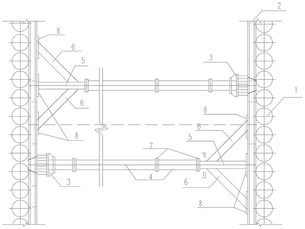
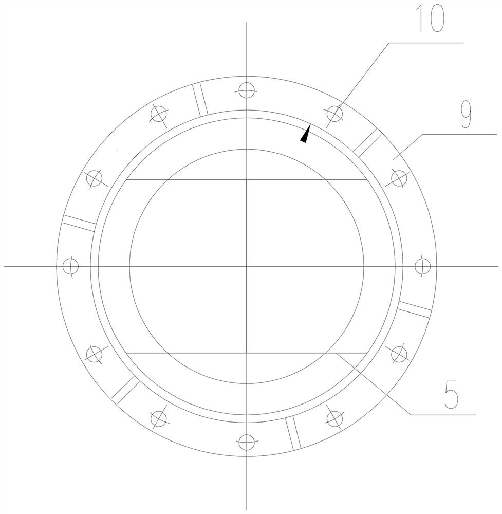
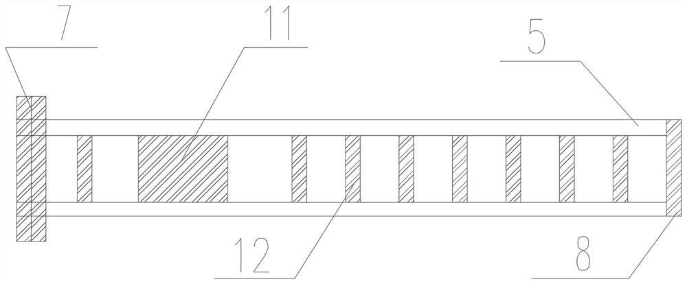
[0044] The present invention relates to a foundation pit support system based on octatimer-based steel, including the horizontal support within the foundation pit, and the support of the foundation pit includes eight-character working text steel support and steel pipe support 4 segments; eight words Type structure steel support includes a diagonal support 6 that is symmetrically arranged on both sides of the support 5 and the support 5; one end of the oblique support 6 is fixed to the surface of the base pit, and the other end is fixed to the side surface of the support 5; support 5 One end is fixed to the sacral 2 or crown beam in the foundation pit, and the other end is mechanically connected to the steel pipe 4; the other end of the steel pipe 4 is fixed to the sacral pit 2 or the crown beam.

[0045] Both the counter 5 and the opposing support 6 are allocated steel, and t...


PUM


Abstract

The invention relates to a foundation pit supporting system based on splayed I-shaped steel and a construction method thereof. The system comprises an inner support horizontally arranged in a foundation pit, wherein the inner support comprises two sections, namely a splayed I-shaped steel support and a steel pipe support; the splayed I-shaped steel support comprises a diagonal support and diagonal braces symmetrically arranged on two sides of the diagonal support; one end of each diagonal brace is fixed to a surrounding purlin or a crown beam in the foundation pit, and the other end of each diagonal brace is fixed to the side face of the diagonal support; one end of the diagonal support is fixed to the surrounding purlin or the crown beam in the foundation pit, and the other end of the diagonal support is connected with the steel pipe support; and the other end of the steel pipe support is fixed to the surrounding purlin or the crown beam in the foundation pit through a movable head. The novel inner support with one or two ends made of the splayed I-shaped steel is designed, so that the action range of each steel support is widened, the number of the inner supports is reduced, the cost is reduced, and the construction period is shortened; and meanwhile, the operation space in the foundation pit can be enlarged, more abundant operation conditions are reserved for large machinery, the earthwork outward transport and material feeding and discharging efficiency is improved, and a more efficient and economical foundation pit steel support system is realized.

Description

Technical field [0001] The present invention relates to the field of underground engineering, and more particularly to a foundation pit support system based on octatiming-based steel. Background technique [0002] With the rapid development of the economy, in order to guide the city's reasonable layout and order development, all kinds of basic structures are continuously emerging, and the general construction period of such foundation pit projects is tight, the safety requirements are high, and currently routine foundation steel The support spacing is too small (general case, the first steel support spacing is 3m, the second road is 6m), resulting in too much amount of the internal support, the construction framework and the post-removal time are longer, the base pit side wall is too long, The construction work is small, there is a certain impact on the safety of the foundation pit, there is a certain safety hazard, and it is increasingly not suitable for current efficient, energ...

Claims


Application Information

Patent Timeline
Patent Type & Authority Applications(China)
IPC IPC(8): E02D17/04
CPCE02D17/04
Inventor 戴志仁王俊李谈胡瑞青杨小兵曹伟
Owner CHINA RAILWAY FIRST SURVEY & DESIGN INST GRP
Why Eureka
Try Eureka