Energy-saving building wall structure
A technology for building walls and bottom beams, applied to building components, building structures, buildings, etc., can solve problems such as less research on walls, high cooling costs, and poor air circulation, so as to avoid human discomfort and reduce cooling costs , to avoid the effect of indoor high temperature
- Summary
- Abstract
- Description
- Claims
- Application Information
AI Technical Summary
Problems solved by technology
Method used
Image

Examples
Embodiment 1
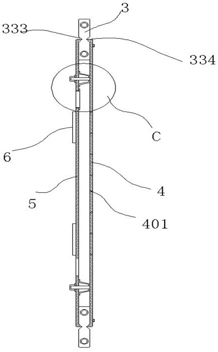
[0039] An energy-saving building wall structure, comprising a bottom beam 1 and a top beam 2; a plurality of columns 3 are arranged between the bottom beam 1 and the top beam 2; two adjacent columns 3 are fitted with A detachable inner panel 4, an outer panel 5 connecting the inner panel 4 is installed between two adjacent columns 3, a ventilation gap is formed between the inner panel 4 and the outer panel 5, and The board surface of the outer panel 5 is provided with more than one air inlet slot 501, and the board surface of the inner panel 4 is provided with an air inlet hole 401 misaligned with the air inlet slot 501; 5, a T-shaped slideway 502 is provided on the side of the air inlet groove 501; a slide door 6 that can slide sideways is fitted through the slideway 502, and the slide door 6 slides to close the The air intake slot 501 is described; the bottom of the outer panel 5 is provided with a drainage gap 551; in the above-mentioned technical scheme, in spring, autumn ...
Embodiment 2
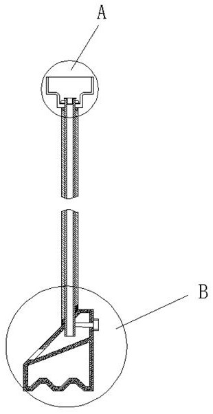
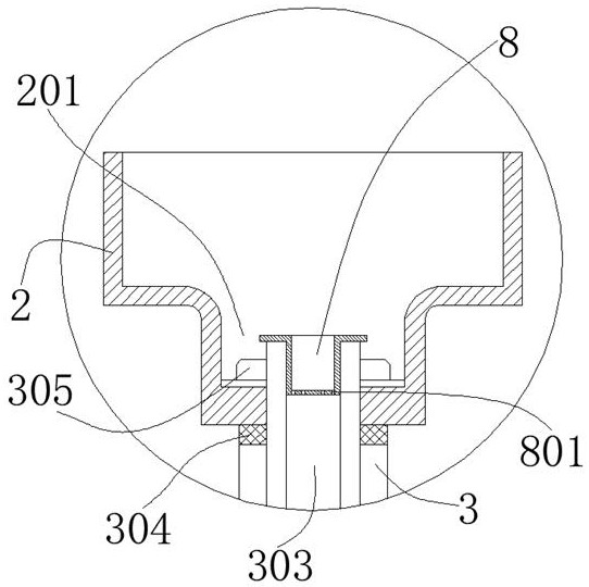
[0041] The upper end of the bottom beam 1 is provided with a slope 101, the end of the slope 101 away from the room is inclined downward, the lower end surface of the column 3 fits the slope 101, between the column 3 and the bottom beam 1 A sealing gasket 301 is interposed; two through holes 302 are vertically penetrated at the top of the column 3, and a reinforcing tube 303 is inserted through the through holes 302; an insertion hole is vertically penetrated on the slope 101 , the lower end of the reinforcing pipe 303 is inserted into the bottom beam 1 through the socket, and a partition 102 is arranged in the bottom beam 1, and a drainage cavity 103 is formed above the partition 102. The side of 101 is provided with the drainage hole 104 that communicates with the drainage cavity 103; the screw 105 for fixing the reinforcing pipe 303 is screwed into the inner side of the bottom beam 1; the middle position of the top beam 2 is provided with a concave Groove 201; the groove bo...
Embodiment 3
[0043] The sliding door 6 has a T-shaped chute 601 matching the slideway 502, a plurality of concave holes 602 are arranged on the inner side of the chute 601, and a spring 603 is arranged in the concave hole 602. , the end of the spring 603 away from the concave hole 602 is against the slideway 502; under the reaction force of the spring 603, the sliding door 6 fits the outer panel 5; The inner wall of 501 is provided with a rubber inner lining 552, the inner lining 552 has a flange portion 553 limited on the inner side of the outer panel 5; the flange portion 553 and the outer panel 5 are glued and fixed , the part of the inner lining ring 552 protrudes to the outside of the air inlet slot 501, when the sliding door 6 slides to close the air inlet slot 501, the spring 603 is compressed, and the sliding door 6 is tight at this time. Paste the inner lining ring 552; the above structure is mainly to increase the sealing performance of the sliding door 6 to the air inlet groove ...
PUM
 Abstract
Description
Claims
Application Information
 - Generate Ideas
- Intellectual Property
- Life Sciences
- Materials
- Tech Scout
- Unparalleled Data Quality
- Higher Quality Content
- 60% Fewer Hallucinations
Browse by: Latest US Patents, China's latest patents, Technical Efficacy Thesaurus, Application Domain, Technology Topic, Popular Technical Reports.
© 2025 PatSnap. All rights reserved.Legal|Privacy policy|Modern Slavery Act Transparency Statement|Sitemap|About US| Contact US: help@patsnap.com