Building structure hole plugging device and method

A technology of building structure and plugging device, which is applied in the direction of building structure, construction, building maintenance, etc., can solve the problems of low plugging efficiency, difficult plugging, high plugging cost, etc., and achieves simple plugging operation, convenient construction, strong practical effect

Pending Publication Date: 2021-06-29
MCC5 GROUP CORP SHANGHAI
View PDF0 Cites 1 Cited by
  • Summary
  • Abstract
  • Description
  • Claims
  • Application Information

AI Technical Summary

Problems solved by technology

[0003] Aiming at the above existing problems, the present invention discloses a building structure hole sealing device and a sealing

Method used


Image

  • Building structure hole plugging device and method
  • Building structure hole plugging device and method

Examples


Example Embodiment

[0024] Example 1:

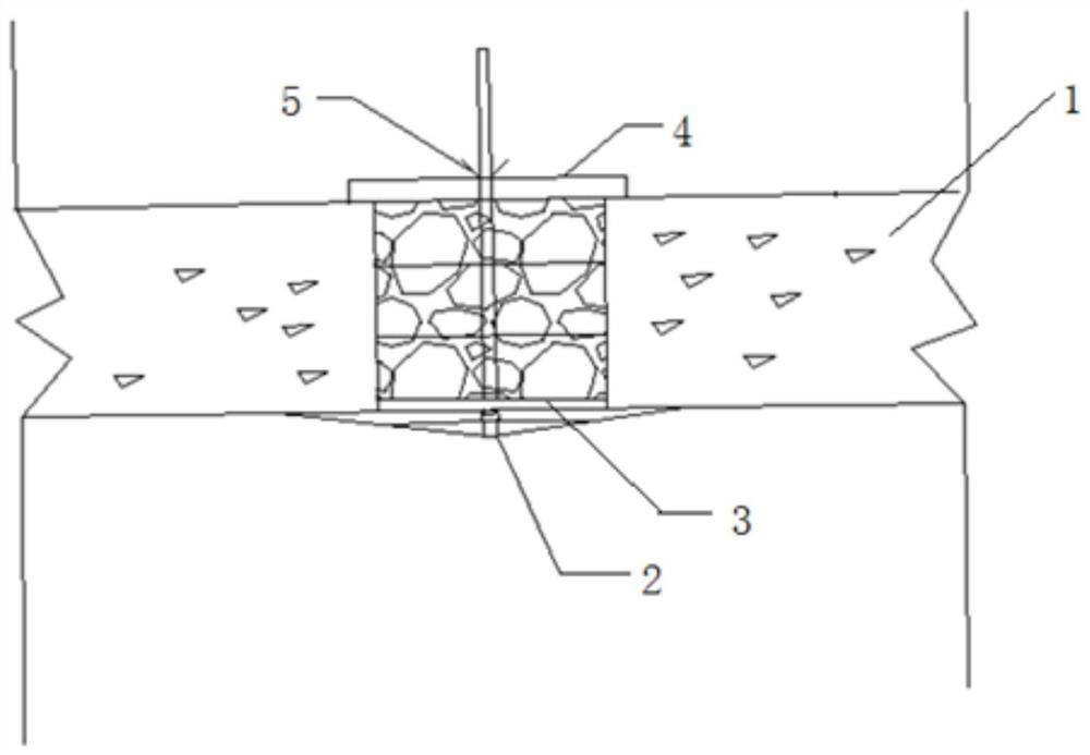
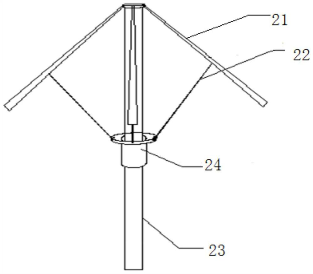
[0025] Such as figure 1 with 2 As shown, the present invention discloses a building structural hole sealing device, which is a floor; specifically, the blocking device comprises an umbrella sealing assembly 2, a reference member 3, a positioning rod 4, and a limit piece 5 The umbrella sealing assembly 2 includes an umbrella 22, an umbrella 3, an umbrella 23, and a tubular slider 24, and the top of the umbrella 23 is active (e.g., hinged), which is disposed on the umbrella 21. There is a umbrella surface, the cylindrical slider 24 is set on the umbrella 23 and slides along the umbrella 23, the cylindrical slider 24 is connected to the umbrella frame 21, and the base line 3 and the hole The lower port shape and dimension are the same (generally a circular panel); the circular portion 3 and the central portion on the positioning rod 4 are perforated, and the reference member 3 is disposed on the umbrella 23 by the perforation sleeve, and the reference member 3 is ...

Example Embodiment

[0029] Example 2:

[0030] The present invention also discloses a block blocking method for building structural structures, and the blocking method is based on the above-described embodiment, and in particular, the method includes the following steps:

[0031] Step S1, after inverting the umbrella sealing device assembly, extends into the hole from the upper port of the hole, so that the umbrella stand is below the building structure.

[0032] Step S2, the reference part is disposed on the umbrella handle through the perforation sleeve, and the reference member slides along the umbrella handle.

[0033] Step S3, the positioning rod is arranged on the umbrella holder, and the positioning rod frame is provided on the top of the hole, that is, the length of the positioning rod is greater than the diameter of the hole, at which time the positioning rod is respectively disposed on both sides of the hole on both sides of the hole. .

[0034] Step S4 is applied to the umbrella handle, an...


PUM


Abstract

The invention relates to the technical field of building construction, in particular to a building structure hole plugging device and method. The building structure hole plugging device comprises an umbrella-shaped plugging device assembly, a reference part, a positioning rod and a limiting part, the umbrella-shaped plugging device assembly is inverted and then stretches into a hole from an upper end opening of the hole, and an umbrella stand is located below a building structure; then the reference part and the positioning rod sequentially sleeve the umbrella handle, and the positioning rod is erected at the top of the hole; then, upward force is applied to the umbrella handle, when the umbrella stand is completely unfolded, the umbrella handle is fixed to the positioning rod through the limiting part, and at the moment, the reference part is located at the lower end opening of the hole; the hole is filled with a plugging material; and the building structure hole can be plugged. The building structure hole plugging operation is simple and convenient, and the time cost and the labor cost are reduced; and in addition, the building structure hole plugging device is low in manufacturing cost, convenient to construct, capable of being recycled and high in practicability.

Description

technical field [0001] The invention relates to the technical field of building construction, in particular to a device and a method for sealing a hole in a building structure. Background technique [0002] At present, when the holes in building structures (such as floor slabs) are abandoned, plugging operations are required. In general, the floor height is high and the space is insufficient. If the traditional method is directly used to hang the formwork, it is necessary to erect simple scaffolding for construction. The floor height Higher movable scaffolds cannot be used, and steel pipe scaffolds can only be erected for construction. The risk factor is high, difficult to operate, low in efficiency, high in labor costs, time-consuming, and increased in engineering costs; these are undesirable for those skilled in the art. arrived. Contents of the invention [0003] In view of the above existing problems, the present invention discloses a building structure hole sealing d...

Claims


Application Information

Patent Timeline
IPC IPC(8): E04G23/02
CPCE04G23/0203E04G23/0211
Inventor 刘涛严俨但伟袁正清
Owner MCC5 GROUP CORP SHANGHAI
Why Eureka
Try Eureka