
Gear pair meshing stiffness calculation method and terminal equipment

A technology of meshing stiffness and calculation method, which is applied in special data processing applications, instruments, electrical digital data processing, etc., and can solve problems such as neglect

Active Publication Date: 2021-06-29
TIANJIN HAISHENG JIAHE ENERGY TECH
View PDF5 Cites 0 Cited by
  • Summary
  • Abstract
  • Description
  • Claims
  • Application Information

AI Technical Summary

Problems solved by technology

[0003] In order to improve the problem of ignoring the influence of friction and wear on the meshing stiffness of involute helical cylindrical gear pairs in the prior art, the purpose of the embodiment of this application is to provide a gear pair meshing stiffness calculation method, terminal equipment and readable storage medium

Method used


Image

  • Gear pair meshing stiffness calculation method and terminal equipment
  • Gear pair meshing stiffness calculation method and terminal equipment
  • Gear pair meshing stiffness calculation method and terminal equipment

Examples


Embodiment Construction

[0077] In order to make the purposes, technical solutions and advantages of the embodiments of the present application clearer, the technical solutions in the embodiments of the present application will be clearly and completely described below in conjunction with the drawings in the embodiments of the present application. Obviously, the described embodiments It is a part of the embodiments of this application, not all of them. The components of the embodiments of the application generally described and illustrated in the figures herein may be arranged and designed in a variety of different configurations.

[0078] Accordingly, the following detailed description of the embodiments of the application provided in the accompanying drawings is not intended to limit the scope of the claimed application, but merely represents selected embodiments of the application. Based on the embodiments in this application, all other embodiments obtained by persons of ordinary skill in the art w...


PUM


Abstract

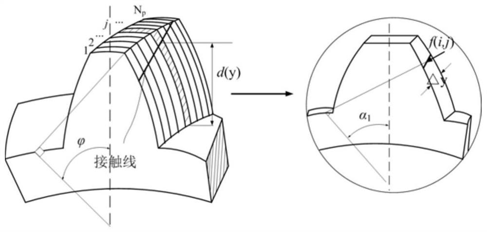
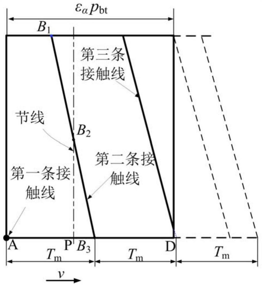
The embodiment of the invention discloses a gear pair meshing rigidity calculation method, which specifically comprises the following steps of: equally dividing single gear teeth in a meshing state according to basic geometric parameters and working condition parameters of a gear pair to obtain a plurality of straight tooth slices; according to the basic geometric parameters and the working condition parameters, calculating the load, the friction coefficient and the abrasion loss of each straight tooth slice; according to the load, calculating the friction coefficient and the abrasion loss, the bending rigidity, the axial compression rigidity and the shearing rigidity through adoption of an energy method; according to the bending rigidity, calculating the axial compression rigidity and the shearing rigidity, the single gear tooth rigidity; calculating meshing stiffness of a single pair of gear teeth according to the tooth stiffness of the single gear; calculating the meshing rigidity of the gear pair according to the meshing rigidity of the single pair of gear teeth; and therefore, the influence of friction and abrasion on the meshing rigidity of the helical gear pair is considered, and the meshing rigidity of the helical gear pair is accurately calculated.

Description

technical field [0001] The invention relates to the technical field of mechanical transmission system dynamics, in particular to a method for calculating the meshing stiffness of a gear pair and a terminal device. Background technique [0002] Helical gears have stable transmission, strong load capacity and high transmission efficiency, so they are widely used in many industrial fields. The time-varying meshing stiffness is one of the main internal excitation sources of the gear transmission system. Accurately obtaining the actual meshing stiffness of the gear is an important prerequisite for dynamic analysis, vibration and noise reduction, and optimal design. During the meshing process of gear pairs, friction and wear on the tooth surfaces are inevitable. At present, the mesh stiffness calculation method mainly considers the influence of wear on the mesh stiffness of the involute spur gear pair. In the calculation of the mesh stiffness of the involute helical gear pair, th...

Claims


Application Information

Patent Timeline
IPC IPC(8): G06F30/17G06F119/14
CPCG06F30/17G06F2119/14
Inventor 韩林刘福聪戚厚军李伟光刘少帅
Owner TIANJIN HAISHENG JIAHE ENERGY TECH
Learn More