A shockproof contact box

A technology of contact box and anti-vibration plate, which is applied in the direction of anti-seismic equipment, guard plate/louver to prevent touching contacts, cooling/ventilation of substation/switchgear, etc., and can solve the problem of temperature rise of contact box

Active Publication Date: 2022-05-03
句容市凯特电力电器有限公司
View PDF0 Cites 0 Cited by
  • Summary
  • Abstract
  • Description
  • Claims
  • Application Information

AI Technical Summary

Problems solved by technology

[0004] Aiming at the deficiencies of the prior art, the present invention provides an anti-vibration contact box to solve the problem that the static contact and the moving contact will move each other when the existing contact box vibrates, which causes the temperature inside the contact box to rise

Method used


Image

  • A shockproof contact box
  • A shockproof contact box

Examples


Embodiment Construction

[0019] The technical solutions in the embodiments shown in the embodiments of the present application will be clearly and completely described below with reference to the drawings in the embodiments shown in the embodiments of the present application.

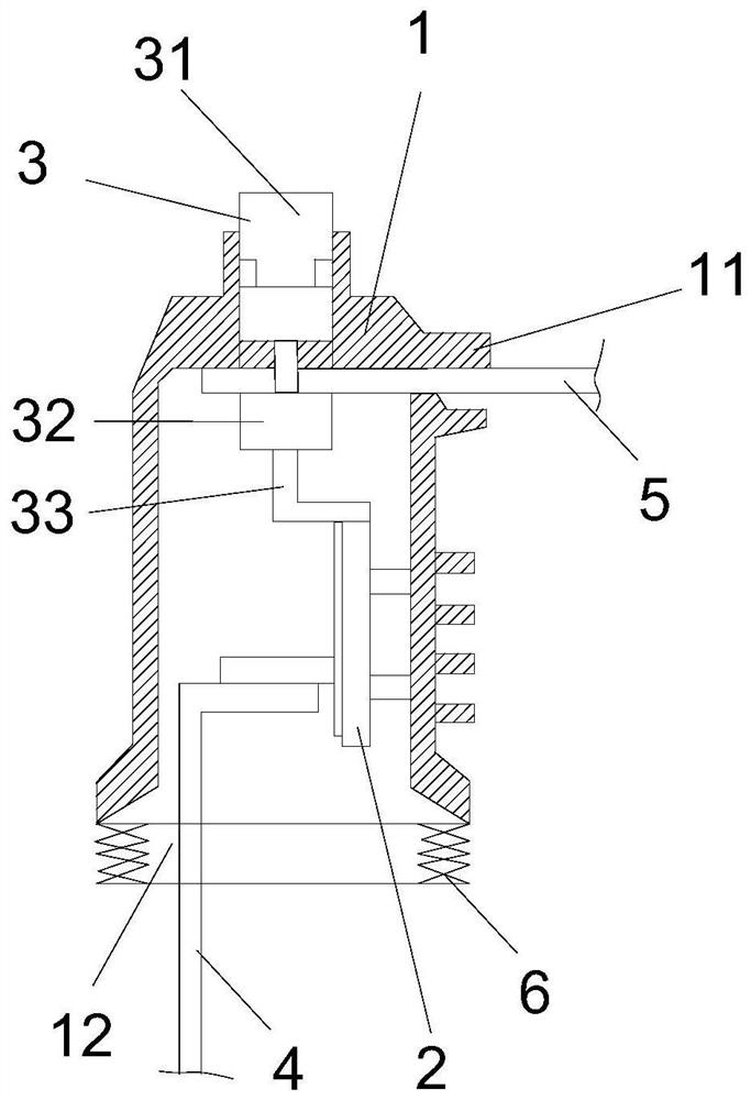
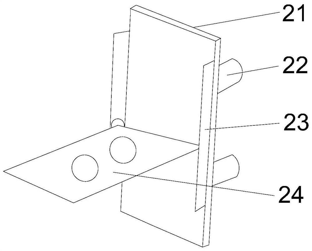
[0020] see Figure 1 to Figure 2 As shown in the schematic diagram, an anti-vibration contact box includes a housing 1, an anti-vibration plate 2, a static contact 3, a moving contact 4, and a bus bar 5; the anti-vibration plate 2 includes a connecting plate 21, a fixed column 22, a slide 23 and a sliding plate 24, the fixed column 22 is located on one side of the connecting plate 21, and the two slide grooves 23 are provided on both sides of the other side of the connecting plate 21, and one end of the sliding plate 24 is close to Along the connecting plate 21, the other end of the sliding plate 24 slides in the chute 23, and the sliding plate 24 is located between one side of the connecting plate 21 and the bottom edge of the...


PUM


Abstract

This application provides a seismic contact box, including shells, seismic boards, static contacts, moving contacts, and bus; seismic boards include connecting boards, fixed columns, sliding papers, and sliding boards.There are two sliding settings, which are located on both sides of the other side of the connector. One end of the sliding board is close to the connecting board.Connect.When using it, when the tentacles are vibrating, the sliding board can slide inside the slide. ThereforeConnection, so it will not cause the area changes in the current channel between the movement of the movement and the static, which will not cause the spark.Movement causes the problem of rising temperature in the contact box.

Description

technical field [0001] The application belongs to the field of contact box equipment, and in particular relates to an anti-vibration contact box. Background technique [0002] The high-voltage switchgear is one of the most important parts of the power system. The busbar system installed in the cabinet is connected to the static contact of the circuit breaker device through the contact box. At present, the contact box and the static contact of the existing high-voltage switchgear are both It is in the shape of a sleeve, and the bottom end of the smaller static contact barrel is fixedly installed in the larger contact box. [0003] The existing contact box includes a cylindrical box body, and a female outlet is installed on the upper part of the box body. Its function is to avoid corona discharge and other phenomena caused by the exposed joints and joints of cabinets. However, the existing contact box is basically just a box body, so it is difficult to avoid equipment vibrat...

Claims


Application Information

Patent Timeline
Patent Type & Authority Patents(China)
IPC IPC(8): H02B1/14H02B1/56H02B1/54
CPCH02B1/14H02B1/56H02B1/54
Inventor 王自发
Owner 句容市凯特电力电器有限公司
Why Eureka
Try Eureka