Laminated core transformer

A laminated iron core and transformer technology, applied in the field of transformers, can solve problems such as emission, reduced service life of transformers, and elevated temperature of transformers

Inactive Publication Date: 2018-01-12
YUNAN JINGCHUANG LIQUID METAL THERMAL CONTROL TECH RES & DEV CO LTD
View PDF5 Cites 0 Cited by
  • Summary
  • Abstract
  • Description
  • Claims
  • Application Information

AI Technical Summary

Problems solved by technology

[0005] The traditional transformer core is mainly made of silicon steel core. Since the increase of silicon content will make the material hard and brittle, the thermal conductivity and toughness will decrease, which is not good for heat dissipation and machining. Therefore, the traditional silicon steel core transformer is not conducive to heat dissipation, thus Causes the temperature of the transformer to rise, and the overheating of the transformer will seriously reduce its service life

Method used


Image

  • Laminated core transformer
  • Laminated core transformer

Examples


Embodiment Construction

[0021] The specific implementation manners of the present invention will be further described in detail below in conjunction with the accompanying drawings and embodiments. The following examples are used to illustrate the present invention, but are not intended to limit the scope of the present invention.

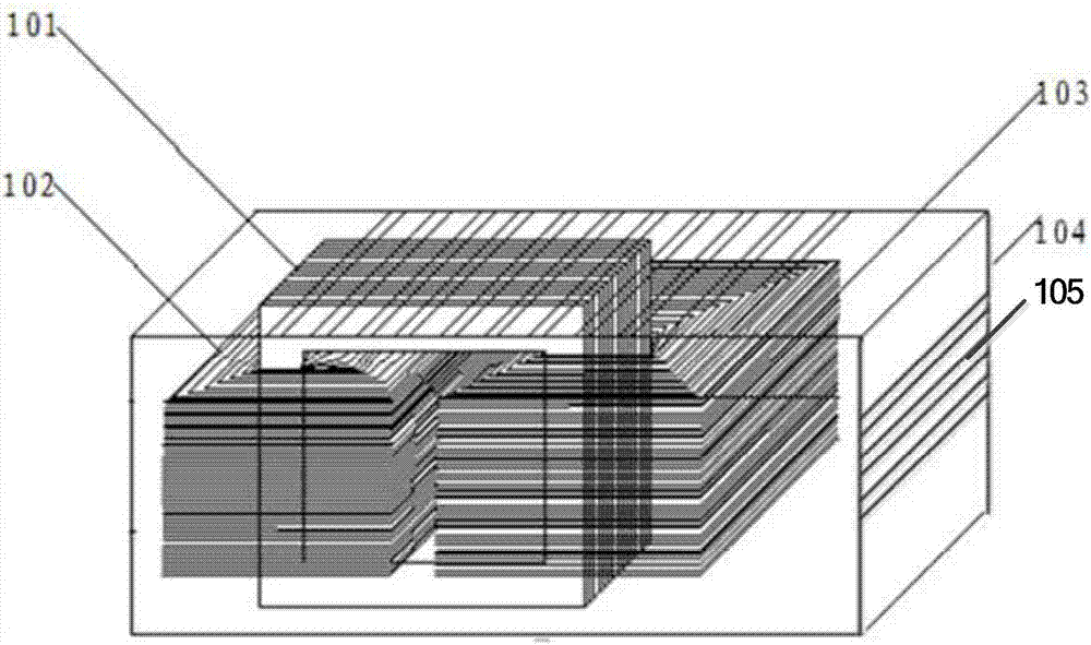
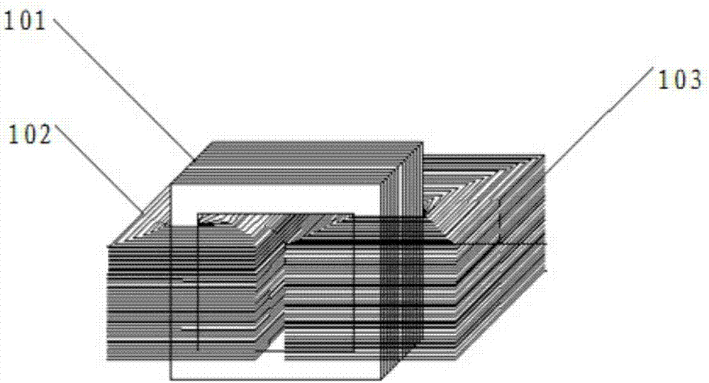
[0022] The line loss generated by the transformer during operation is converted into heat energy, which makes the transformer heat up. The heat emitted is dissipated to the surrounding cooling medium through conduction, convection and radiation. The heat of the transformer mainly comes from the laminated iron core, primary winding and secondary winding. Only when there is a certain temperature difference between the laminated iron core, primary winding and secondary winding can heat be dissipated, so the temperature of each part of the transformer is different. Generally speaking, the temperature of the primary winding and secondary winding is the highest, followed by the...


PUM


Abstract

The invention provides a laminated core transformer. The material for a laminated core in a transformer is liquid metal. The laminated core of the laminated core transformer is made of the liquid metal, the heat produced in the working process of the laminated core transformer dissipates by utilizing the low loss, high permeability and high thermal conductivity of the liquid metal and is quickly transferred to the outside through the laminated core made of the liquid metal, the laminated core, a primary winding and a secondary winding form large temperature difference, and accordingly the working temperature of the transformer is reduced. The problem that the temperature of a traditional silicon steel core transformer rises due to heat is solved, and the service life of the transformer isprolonged.

Description

technical field [0001] The present invention relates to the field of transformers, and more particularly, to laminated core transformers. Background technique [0002] At present, as an important type of renewable green energy, electric energy is widely used in modern industries, and the electric energy generated by power plants often needs to be transmitted over long distances to reach the power-consuming area. Long-distance electric energy transmission adopts the method of high voltage and low current, because the voltage drop is proportional to the current, and the line loss of electric energy during long-distance transmission is proportional to the square of the current, so a higher transmission voltage can obtain lower line voltage drop and line loss. Due to the manufacture of high-voltage generators, it is currently technically difficult to achieve. Therefore, in the process of electric energy transmission, a relatively low voltage is first obtained through the gener...

Claims


Application Information

Patent Timeline
Patent Type & Authority Applications(China)
IPC IPC(8): H01F27/245H01F27/30H01F27/02H01F27/08
Inventor 任文兵盛磊刘静
Owner YUNAN JINGCHUANG LIQUID METAL THERMAL CONTROL TECH RES & DEV CO LTD
Why Eureka
Try Eureka