Refrigerator control method and refrigerator

A control method and refrigerator technology, which is applied to household refrigerators, household refrigeration devices, defrosting, etc., can solve the problems of high energy consumption for defrosting and temperature rise in refrigerated rooms, so as to reduce the burden on the power grid, solve the problem of temperature rise, Power saving effect

Active Publication Date: 2022-06-28
GREE ELECTRIC APPLIANCES INC
View PDF5 Cites 0 Cited by
  • Summary
  • Abstract
  • Description
  • Claims
  • Application Information

AI Technical Summary

Problems solved by technology

However, in the defrosting process of existing air-cooled refrigerators, the defrosting energy consumption is large. During the defrosting process, the compressor stops and the heat generated by the defrosting heater causes the temperature of the refrigerating room to rise. Therefore, it is necessary to provide a method that can reduce the defrosting energy consumption. A refrigerator that reduces the impact of the defrosting process on the temperature of the refrigerated compartment

Method used


Image

  • Refrigerator control method and refrigerator
  • Refrigerator control method and refrigerator
  • Refrigerator control method and refrigerator

Examples


Embodiment Construction

[0041] In the description of the present invention, it should be noted that the orientation or positional relationship indicated by the terms "inside", "outside", etc. is based on the orientation or positional relationship shown in the accompanying drawings, and is only for the convenience of describing the present invention and simplifying the description, It is not intended to indicate or imply that the device or element referred to must have a particular orientation, be constructed and operate in a particular orientation, and therefore should not be construed as limiting the invention.

[0042] In the description of the present invention, it should be noted that, unless otherwise expressly specified and limited, the terms "installed", "connected", "connected", "contacted" and "connected" should be understood in a broad sense, for example, it may be The fixed connection can also be a detachable connection or an integral connection; it can be a mechanical connection or an elec...


PUM


Abstract

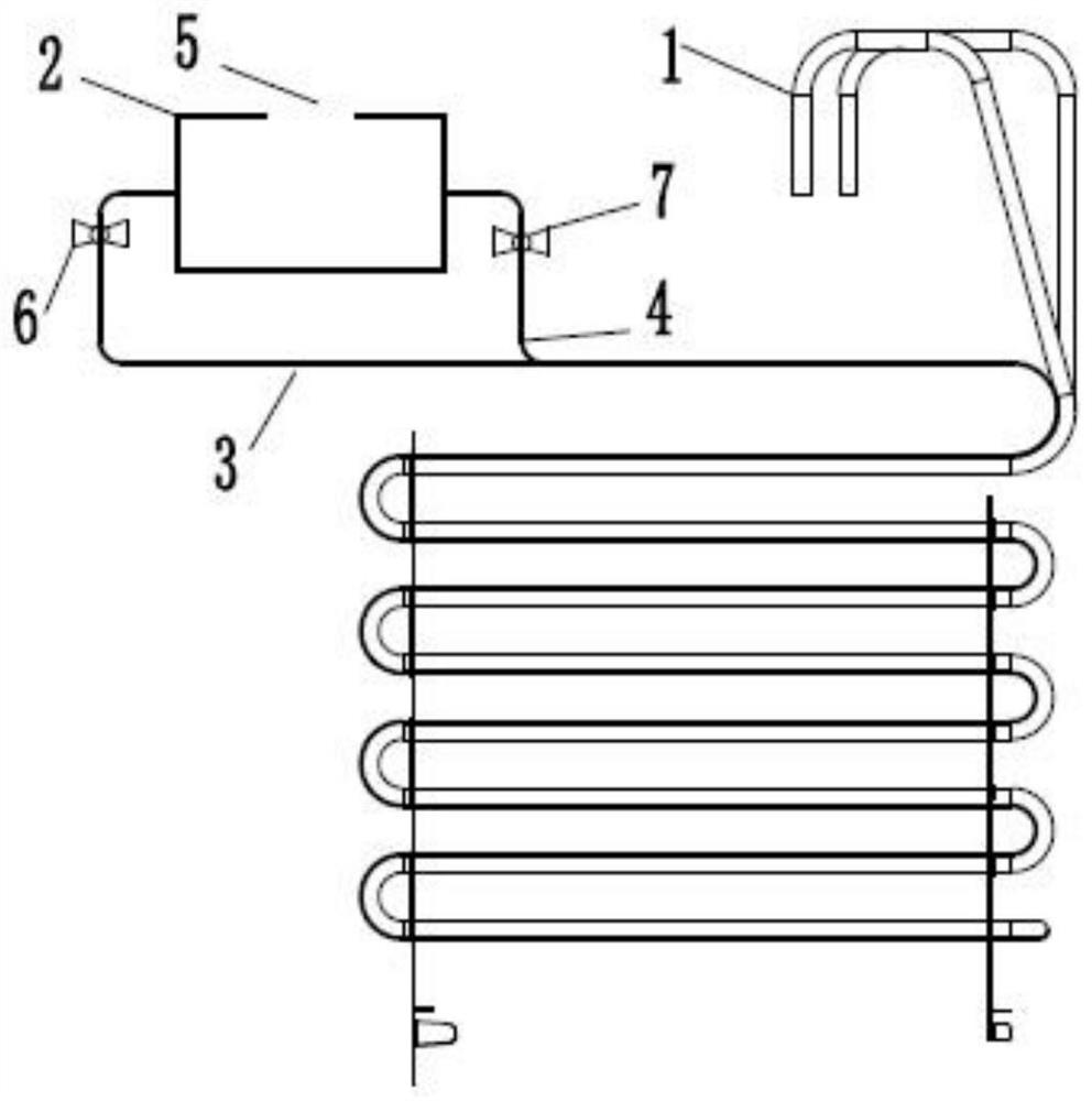
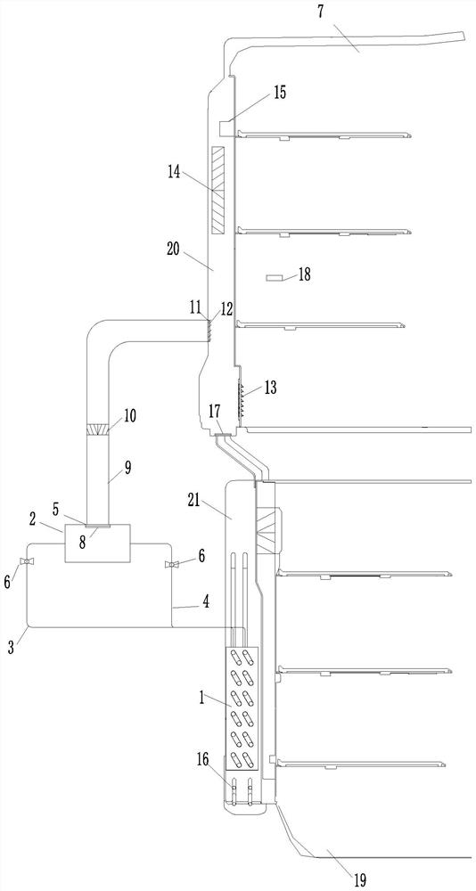
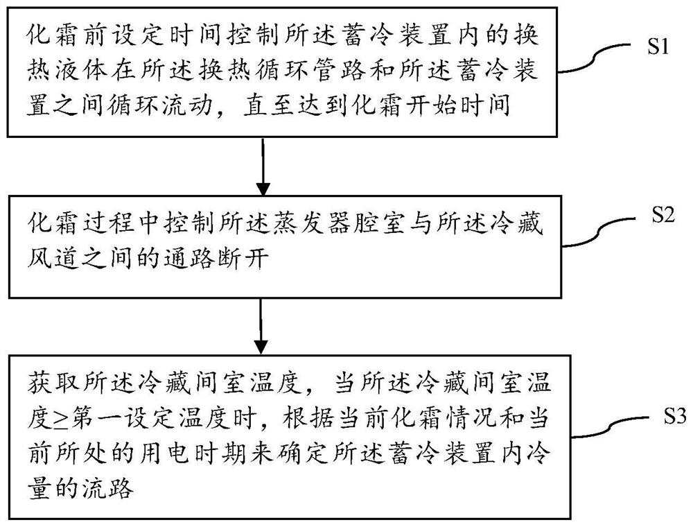
The invention belongs to the technical field of refrigerators, and particularly relates to a refrigerator and a control method. A refrigerating chamber of the refrigerator is provided with an air inlet and an air outlet; two ends of the refrigeration air duct are respectively connected with the air inlet and the air outlet, and a circulating air path is formed between the refrigeration air duct and the refrigeration chamber; an evaporator is arranged in the evaporator chamber, and the evaporator chamber is connected with the refrigeration air duct in an on-off mode; the cold storage module comprises a cold storage device, a cold output pipeline and a heat exchange circulation pipeline. The cold storage device is connected with the cold output pipeline and the heat exchange circulation pipeline in an on-off mode. The cooling capacity output pipeline is communicated with the refrigeration air duct, and the heat exchange circulation pipeline is thermally coupled with the evaporator; heat exchange liquid is contained in the cold storage device, and the heat exchange liquid can be controlled to enter the heat exchange circulation pipeline from the cold storage device to exchange heat with the evaporator; and the cold energy stored by the cold storage device can be controlled to enter the refrigeration air duct from the cold energy output pipeline. According to the refrigerator and the control method, the defrosting energy consumption can be reduced, and the influence of the defrosting process on the temperature of the refrigerating chamber is reduced.

Description

technical field [0001] The invention belongs to the technical field of refrigerators, and in particular relates to a control method of a refrigerator and a refrigerator. Background technique [0002] Compared with direct-cooling refrigerators, air-cooled refrigerators have been favored by consumers in the market in recent years because of their automatic frost function, which eliminates the trouble of manual defrosting and greatly improves the convenience of users. Air-cooled refrigerators generally use heaters to defrost. When a large amount of frost layer is condensed on the surface of the evaporator, in order to ensure the normal operation of the system and refrigeration, it is necessary to turn on the heater to heat the frost layer by means of thermal radiation to achieve defrosting. Cream purpose. However, in the defrosting process of the existing air-cooled refrigerators, the defrosting energy consumption is large. During the defrosting process, the compressor shuts d...

Claims


Application Information

Patent Timeline
Patent Type & Authority Applications(China)
IPC IPC(8): F25D11/00F25D17/06F25D21/12F25D29/00
CPCF25D11/006F25D17/06F25D21/12F25D29/005Y02E60/14
Inventor 柳诗语李琦辛海亚张玉昊翟照阳
Owner GREE ELECTRIC APPLIANCES INC
Why Eureka
Try Eureka