Photocatalytic denitration testing system and using method thereof

A test system and photocatalytic technology, applied in the field of photocatalytic denitrification, can solve the problems of large land occupation, low denitrification activity, complex device structure and operation, etc., and achieve the effect of convenient operation process, simple device and stable gas path

Pending Publication Date: 2021-07-27
SICHUAN UNIV
View PDF8 Cites 0 Cited by
  • Summary
  • Abstract
  • Description
  • Claims
  • Application Information

AI Technical Summary

Problems solved by technology

[0004] In view of the above-mentioned deficiencies or defects, the purpose of the present invention is to provide a photocatalytic denitrification test system and its use method, which can effectively solve the problems of complex device structure and operation, large footprint and low denitrification activity existing in existing test devices. At the same time, it can realize the screening of laboratory photocatalysts and the photocatalytic denitrification reaction of continuous flow, low flow and low concentration

Method used


Image

  • Photocatalytic denitration testing system and using method thereof

Examples


Embodiment 1

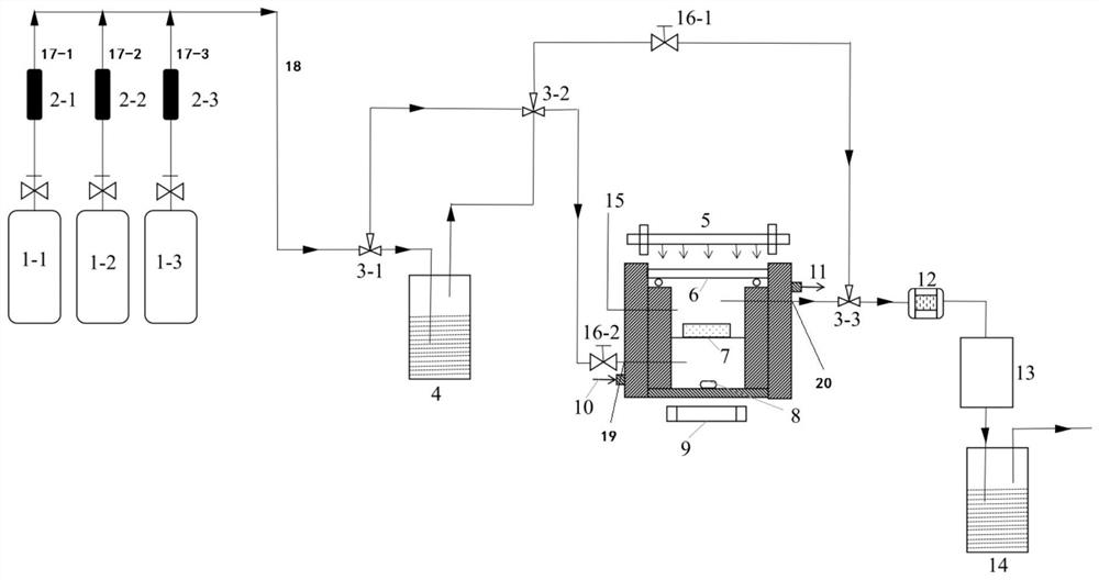
[0034] For the photocatalytic denitrification test, the gas used in the gas storage cylinder includes nitrogen 1-1, nitrogen monoxide 1-2, and oxygen 1-3. The three gases contained in the gas storage cylinder pass through the respective pipelines (17-1 , Nitrogen gas intake pipeline; 17-2, Nitric oxide intake pipeline; 17-3, Oxygen intake pipeline) delivery, the gas flow of each pipeline passes through the respective flow controllers with display functions (2-1, flow rate Controller one; 2-2, flow controller two; 2-3, flow controller three) monitor and regulate respectively; after that, nitrogen 1-1, nitric oxide 1-2, oxygen 1-3 three-way gas confluence is A mixed gas inlet main path 18, after which the mixed gas has two branch paths, one is the normal test process, and the other is a bypass for adjustment and emergency; first close the main path gas path control of the gas path passing through the reaction chamber The valve 16-2 opens the bypass gas path control valve 16-1 on...

Embodiment 2

[0036] For the water-based photocatalytic denitrification test, the gas used in the gas storage cylinder includes nitrogen 1-1, nitric oxide 1-2, and oxygen 1-3, and the water vapor is provided by the saturated humidification device 4 . The three-way gas contained in the gas storage cylinder is transported through its own pipeline, and the gas flow of each pipeline is monitored and regulated by the flow controller with its own display function. After that, nitrogen 1-1, nitric oxide 1-2, The oxygen 1-3 three-way gas merges into a mixed gas inlet main road 18, and then the mixed gas passes through the saturated humidifying device 4 to become waste gas containing a certain amount of moisture. The mixed gas with water vapor has two branches, one is the normal test process, and the other is the bypass for adjustment and emergency; firstly close the main gas path control valve 16-2 of the gas path passing through the reaction chamber and open the bypass path. The bypass gas path co...


PUM

PropertyMeasurementUnit
Diameteraaaaaaaaaa
Heightaaaaaaaaaa

Abstract

The invention discloses a photocatalytic denitration testing system and a using method. The photocatalytic denitration testing system mainly comprises a gas inlet system, a reaction system, a tail gas treatment system and an automatic control system. The reaction system comprises a magnetic stirrer, a reaction chamber and a xenon lamp device. The magnetic stirrer is located below the reaction chamber, and the xenon lamp device is located above the reaction chamber; the top of the reaction chamber is a glass plate, a temperature monitor and a stirrer are arranged in the reaction chamber, one side of the reaction chamber is provided with a cooling circulating water inlet and an air inlet connector, the other side of the reaction chamber is provided with a cooling circulating water outlet and an air outlet connector, and the air inlet system is connected with the air inlet connector of the reaction chamber through an air inlet pipeline. The tail gas treatment system is connected with a gas outlet interface of the reaction chamber; the problems that an existing testing device is complex in structure and operation, large in occupied area and low in denitration activity can be effectively solved, and meanwhile screening of laboratory photocatalysts and continuous flow low-flow low-concentration photocatalytic denitration reaction can be achieved.

Description

technical field [0001] The invention relates to the technical field of photocatalytic denitrification, in particular to a photocatalytic denitrification test system and a use method thereof. Background technique [0002] With the rapid development of science, technology and economy in modern society, the society's demand for energy consumption is increasing, and the air pollutants from iron and steel enterprises, thermal power plants and other industries are also increasing, especially the ultra-high emission of nitrogen oxides (NOx), which brings A series of environmental problems can even endanger human health, and air pollution cannot be underestimated. With the improvement of people's environmental awareness, my country has begun to take active measures to solve nitrogen oxide pollution. After years of continuous research and exploration, a series of new denitrification technologies have been developed, such as low-temperature SCR denitrification technology, SNCR denitr...

Claims


Application Information

Patent Timeline
IPC IPC(8): G01N31/10G01N21/3504B01D53/86B01D53/56
CPCG01N31/10G01N21/3504B01D53/8625B01D53/8631B01D2255/802
Inventor 郭家秀沈婷周后任袁山东李建军
Owner SICHUAN UNIV
Why Eureka
Try Eureka