
Extrusion-stretch composite forming equipment for forming large-scale cone

A compound forming and extrusion stretching technology, applied in the direction of metal extrusion dies, etc., can solve the problems of large number of die sets, low weld strength, and low component performance, so as to reduce production costs, improve mechanical properties, and shorten the manufacturing process Effect

Active Publication Date: 2022-05-31
ZHONGBEI UNIV
View PDF20 Cites 0 Cited by
  • Summary
  • Abstract
  • Description
  • Claims
  • Application Information

AI Technical Summary

Problems solved by technology

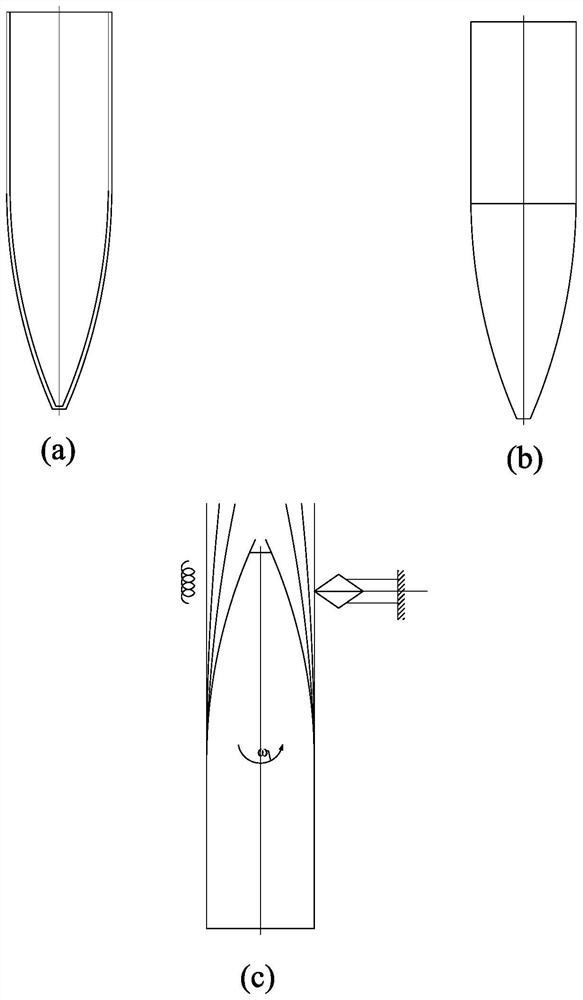
[0003] like figure 1 (b), the stamping method is to process the components in sections, the straight wall part is welded by sheet metal rolling, the tapered head part is stretched by sheet metal, and then the straight wall and the tapered head are welded to complete, but this process flow Many, low weld strength, difficult to meet the requirements of high mechanical properties of large pressure vessels
[0004] like figure 1 (c), the multi-pass spinning forming process uses tubular parts as blanks, heats them while rotating, and performs multiple spinning on the tube body by the rotary wheel, which takes a long time and low efficiency
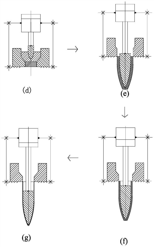
[0005] like figure 2 , Thinning and stretching method, after the bar material is reverse-extruded into a preformed thick-walled tube, it is subjected to multiple wall thickness thinning and stretching, the number of mold sets is large, the cost is high, the number of stretching times is large, the material is heated many times, and the grains are coarse , the component performance is low, the production efficiency is low, and it cannot be used for mass production
[0006] The problems of low strength and low efficiency in the processing of the above-mentioned large cone-shaped components

Method used


Image

  • Extrusion-stretch composite forming equipment for forming large-scale cone
  • Extrusion-stretch composite forming equipment for forming large-scale cone
  • Extrusion-stretch composite forming equipment for forming large-scale cone

Examples


Embodiment Construction

[0031] The present invention will be described in detail below in conjunction with the accompanying drawings and specific embodiments.

[0032] like Figure 1-10 As shown, the present invention provides an extrusion-stretch composite forming equipment for forming a large cone, including a die die 1, a central axis cylinder 2, an annular pressure cylinder 3, a central axis plunger 4, an annular plunger 5, and a mold The punch 6 and the annular pressure ring 7, the middle part of the die die 1 is a through forming channel 10, the diameter of the forming channel 10 is gradually gathered from top to bottom for the deformation of the blank, the central axis press cylinder 2 and the ring press cylinder 3 are coaxial Set up and set up on the forming channel 10 up and down respectively, the lower parts of the central axis cylinder 2 and the annular pressure cylinder 3 are respectively connected with the central axis plunger 4 and the annular plunger 5, and the central axis cylinder 2 ...


PUM


Abstract

The invention discloses an extrusion-stretching compound forming equipment for forming a large cone cylinder, which comprises a die die, a central axis press cylinder, an annular press cylinder, a central axis plunger, an annular plunger, a mold punch and an annular pressure ring, and a mold The middle part of the concave die is a through forming channel. The diameter of the forming channel is gradually gathered from top to bottom for the deformation of the blank. The central axis press cylinder and the annular press cylinder are arranged on the same axis and are erected up and down on the forming channel. The central axis press cylinder and the The lower part of the annular pressure cylinder is connected to the central axis plunger and the annular plunger respectively. The middle part of the annular pressure cylinder is a through plunger channel, and the central axis plunger passes through the plunger channel. The mold punch, annular pressure ring and mold die form the upper part of the blank. The closed space of the mold punch and the annular pressure ring drive the blank to be extruded downward from the forming channel. The shape of the mold punch is consistent with the inner cavity of the cone, and the gap between the mold punch and the forming channel is the blank forming cone. wall thickness. The invention is a device capable of manufacturing high-performance thin-walled tubes once formed.

Description

technical field [0001] The invention relates to the technical field of forming large components, in particular to an extrusion-stretching composite forming device for forming a large cone. Background technique [0002] Large cone-shaped components (see figure 1 (a) As a common load-bearing component, it is widely used in equipment. At present, the traditional forming processes for preparing large cone-shaped components are stamping method, spinning method, casting method and extrusion method. [0003] like figure 1 (b), the stamping method is to process the components in sections, the straight wall part is welded by sheet metal rolling, the tapered head part is stretched by sheet metal, and then the straight wall and the tapered head are welded to complete, but this process flow Many, low weld strength, difficult to meet the requirements of high mechanical properties of large pressure vessels. [0004] like figure 1 (c), the multi-pass spinning forming process uses a tu...

Claims


Application Information

Patent Timeline
Patent Type & Authority Patents(China)
IPC IPC(8): B21C23/03B21C25/02
CPCB21C23/03B21C25/02
Inventor 张治民李国俊白雪智
Owner ZHONGBEI UNIV
Learn More