Three string movable tooth transmission mechanism and its reducer

A three-string movable tooth and transmission mechanism technology, which is applied in the field of movable tooth transmission, can solve complex problems and achieve the effects of simple processing and manufacturing, long life and wide transmission ratio range

Active Publication Date: 2022-04-12
YANSHAN UNIV
View PDF5 Cites 2 Cited by
  • Summary
  • Abstract
  • Description
  • Claims
  • Application Information

AI Technical Summary

Problems solved by technology

[0004] In view of the above problems, the present invention innovatively proposes a three-chord movable tooth transmission mechanism. Compared with the structure of the existing string-line movable tooth transmission, that is, the centerline of the tooth profile where the center of the movable tooth is located is two chord lines and a straight line, the three-chord The movable tooth transmission adopts a new structural form, that is, the center line of the tooth profile where the center of the movable tooth is located is three chord lines, and the movable tooth is also three parts, but its transmission principle is different from the existing string movable tooth transmission. It is more complicated than the calculation method, but when the reduction ratio is constant, the number of movable teeth of the single-stage mechanism is much larger than that of the existing string-line movable tooth transmission mechanism, which greatly improves the carrying capacity and makes the output Torque is more stable

Method used


Image

  • Three string movable tooth transmission mechanism and its reducer
  • Three string movable tooth transmission mechanism and its reducer
  • Three string movable tooth transmission mechanism and its reducer

Examples


Embodiment 2

[0092] In the second embodiment, the movable tooth 10 and the movable tooth 15 both adopt steel balls with a diameter of 10 mm.

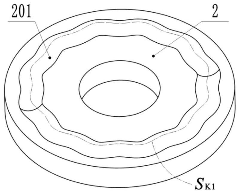
[0093] Figure 10 Among them, the tooth profile centerline S corresponding to the primary tuning line raceway 701 in the second embodiment K1 The plane Cartesian coordinate parametric equation of is:

[0094]

[0095] Figure 11 Among them, the tooth profile centerline S corresponding to the primary shock chord line raceway 801 in the second embodiment H1 The plane Cartesian coordinate parametric equation of is:

[0096]

[0097] Figure 12 Among them, the tooth profile centerline S corresponding to the first-stage moving string raceway 901 in the second embodiment K2 The plane Cartesian coordinate parametric equation of is:

[0098]

[0099] It can be known from the above expression that the primary shock string raceway 801 (or S H1 ) wave number is 2, and the number of first-level movable teeth 10 is 14, then the first-level tuning...

Embodiment 1

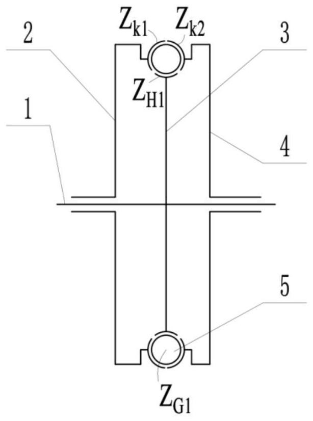
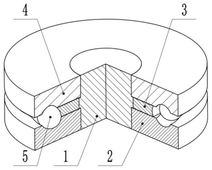
[0107] Embodiment 1 and Embodiment 2 respectively provide the schematic diagram of the single-stage three-chord movable tooth transmission mechanism and the two-stage serial three-chord movable tooth transmission mechanism, the structural diagram of the transmission unit and the structural diagram of the parts with string raceways in the transmission unit , so in the subsequent embodiments of the single-stage or double-stage three-chord movable tooth transmission mechanism, only a schematic diagram of the mechanism and a diagram of the transmission unit can be provided to illustrate the structure, and there is no need to provide a structural diagram of the parts with string raceways.

[0108] Figure 16 and Figure 17 It is the third embodiment of the present invention, which is a two-stage parallel three-chord movable tooth transmission mechanism, wherein, Figure 16 The schematic diagram of the two-stage parallel three-chord movable tooth transmission mechanism is given, ...

Embodiment 3

[0109] In the third embodiment, the movable tooth 10 adopts a steel ball with a diameter of 10 mm, and the movable tooth 15 adopts a steel ball with a diameter of 9 mm.

[0110] The tooth profile centerline S corresponding to the primary tuning line raceway 701 of the third embodiment K1 The plane Cartesian coordinate parametric equation of is:

[0111]

[0112] The centerline S of the tooth profile corresponding to the primary shock chord line raceway 801 in the third embodiment H1 The plane Cartesian coordinate parametric equation of is:

[0113]

[0114] The centerline S of the tooth profile corresponding to the primary moving string raceway 901 of the third embodiment K2 The plane Cartesian coordinate parametric equation of is:

[0115]

[0116] It can be seen from the above expression that the primary shock string raceway 801 (or S H1 ) wave number is 2, and the number of first-level movable teeth 10 is 14, then the first-level tuning wire raceway 701 (or S ...


PUM


Abstract

The invention discloses a three-string movable tooth transmission mechanism and a reducer thereof. The three-string movable tooth transmission mechanism includes a drive shaft, a tuning wire wheel, a shock wave string wheel, a moving string wheel and a movable tooth. The centerline of the tooth profile where the movable tooth center of the three-string movable tooth transmission mechanism is located is three chord lines, and a plurality of movable teeth are arranged between the chord line tooth profiles on the tuning wheel, the shock wave string wheel and the moving string wheel, each The centers of the movable teeth are simultaneously set on the tooth profile centerlines corresponding to the three chord line tooth profiles. The transmission principle of the present invention is different from the existing string movable tooth transmission, and the calculation expression of the reduction ratio can be accurately determined. Moreover, under the condition that the reduction ratio is constant, the number of movable teeth of the single-stage mechanism is increased compared with the number of movable teeth in the existing chordal movable tooth transmission mechanism, thereby improving the bearing capacity and making the output torque more stable.

Description

technical field [0001] The invention relates to the technical field of movable tooth transmission, in particular to a three-chord movable tooth transmission mechanism and a reducer thereof, in particular to a single-stage three-chord movable tooth transmission mechanism, a double-stage three-chord movable tooth transmission mechanism, a two-stage A series reducer and a two-stage parallel reducer. Background technique [0002] There are many branches of movable tooth transmission, and the two commonly used ones are cycloidal movable tooth transmission and chord movable tooth transmission. The soul of these two transmission forms lies in the centerline of the tooth profile meshing with the movable tooth. At the same time, it moves in different tooth profile centerlines to complete the conversion of mechanism motion. The centerline of the tooth profile can be a cycloid, a chord, a straight line, or a line with a length of zero, that is, a point; for example, the patent No. 202...

Claims


Application Information

Patent Timeline
Patent Type & Authority Patents(China)
IPC IPC(8): F16H35/16
CPCF16H35/16
Inventor 许立忠闫济东
Owner YANSHAN UNIV
Why Eureka
Try Eureka