
Output power control circuit, control chip and power supply system

A technology of output power and control circuit, which is applied in the direction of control/regulation system, output power conversion device, circuit device, etc. It can solve the problems of reducing battery discharge time, high battery circuit loss, and affecting service life.

Active Publication Date: 2021-07-02
SHANGHAI XINLONG SEMICON TECH CO LTD
View PDF6 Cites 0 Cited by
  • Summary
  • Abstract
  • Description
  • Claims
  • Application Information

AI Technical Summary

Problems solved by technology

At this time, the battery has a large discharge current, which will cause a high temperature rise of the battery and affect its service life.
Moreover, when the voltage at both ends of the battery is relatively low, the energy stored in the battery is relatively small (take a single-cell lithium battery as an example, when the voltage at both ends of the battery is between 3.7V and 4.2V, the battery stores about 80% of the energy, and the battery at both ends When the voltage is below 3.7V, the energy stored in the battery is very little), at this time the battery maintains a large discharge current, which will further increase the energy consumption rate of the battery, thereby reducing the discharge time of the battery, that is, reducing the working time of the battery and reducing battery life
In addition, a large discharge current will cause a high circuit loss of the battery, resulting in a low overall efficiency of the lighting system, which further reduces the battery life and affects the user experience.

Method used


Image

  • Output power control circuit, control chip and power supply system
  • Output power control circuit, control chip and power supply system
  • Output power control circuit, control chip and power supply system

Examples


Embodiment Construction

[0033] The present invention will be further described in detail below in conjunction with the accompanying drawings and embodiments. It should be understood that the specific embodiments described here are only used to explain the present invention, but not to limit the present invention. In addition, it should be noted that, for the convenience of description, only some structures related to the present invention are shown in the drawings but not all structures.

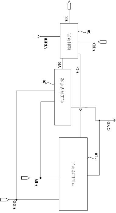
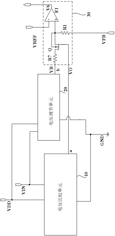
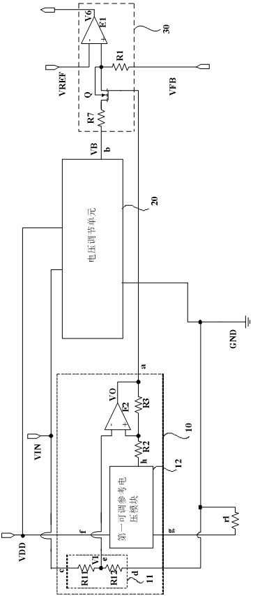
[0034] figure 1 It is a schematic structural diagram of an output power control circuit provided by an embodiment of the present invention. Such as figure 1 As shown, the output power control circuit includes: a voltage regulation unit 20, a voltage comparison unit 10 and a control unit 30; the voltage regulation unit 20 and the voltage comparison unit 10 are connected to the input end of the power chip, and the voltage regulation unit 20 is used to The input voltage VIN forms the first voltage signal VB; the vo...


PUM


Abstract

The embodiment of the invention discloses an output power control circuit, a control chip and a power supply system. The output power control circuit is provided with a voltage regulation unit, a voltage comparison unit and a control unit, wherein the voltage regulation unit forms a first voltage signal according to the input voltage of a power supply chip, the first voltage signal is in negative correlation with the input voltage of the power supply chip, the voltage comparison unit outputs a comparison signal according to the input voltage of the power supply chip and a first reference voltage, the control unit forms a control signal according to the first voltage signal, the comparison signal and a feedback signal of the output current of the power supply chip, and the control signal is used for controlling the state of a power tube of the power supply chip to adjust the output power of the power supply chip; and therefore, the output power can be adjusted according to the input voltage, the problem that when the input voltage is changed to be low, the output power is kept unchanged, so that the discharging current of the battery is increased, and the endurance and the service life of the battery are affected is solved, the endurance of the battery is improved, and the service life of the battery is guaranteed.

Description

technical field [0001] The embodiments of the present invention relate to the technical field of control circuits, and in particular to an output power control circuit, a control chip, and a power supply system. Background technique [0002] In the field of lighting applications where the battery is used as the power supply terminal, the voltage at both ends of the battery continues to drop during the discharge process. When the power of the load remains constant, the discharge current of the battery will continue to rise to maintain the power required by the load. From the voltage at both ends of the battery U=E-IR (where U is the voltage at both ends of the battery, E is the electromotive force of the battery, I is the discharge current of the battery, and R is the internal resistance of the battery), it can be known that when the discharge current of the battery increases, the battery The voltage at both ends drops further, so that the battery further increases the discha...

Claims


Application Information

Patent Timeline
IPC IPC(8): H02M3/156H02M1/08H02M1/32H02J7/00
CPCH02M1/08H02M1/32H02M3/156H02J7/00309H02J7/007182
Inventor 王琦桀刘彬李瑞平
Owner SHANGHAI XINLONG SEMICON TECH CO LTD
Learn More