Multi-station fusion type transformer substation multifunctional fire fighting equipment
A fire-fighting equipment and integrated technology, applied in the direction of fire rescue, etc., can solve the problems of high renovation cost, fixed working range of fire-fighting equipment, and small scope of application.
- Summary
- Abstract
- Description
- Claims
- Application Information
AI Technical Summary
Problems solved by technology
Method used
Image
Examples
Embodiment 1
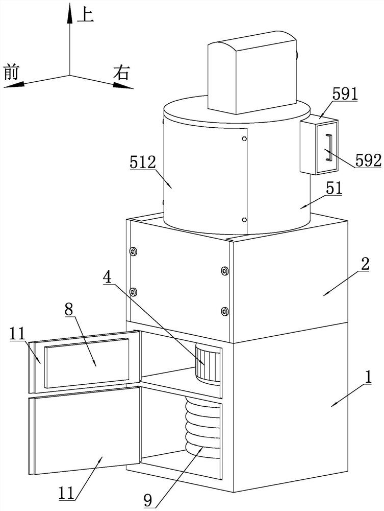
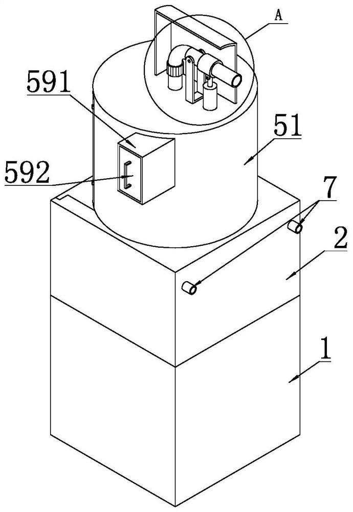
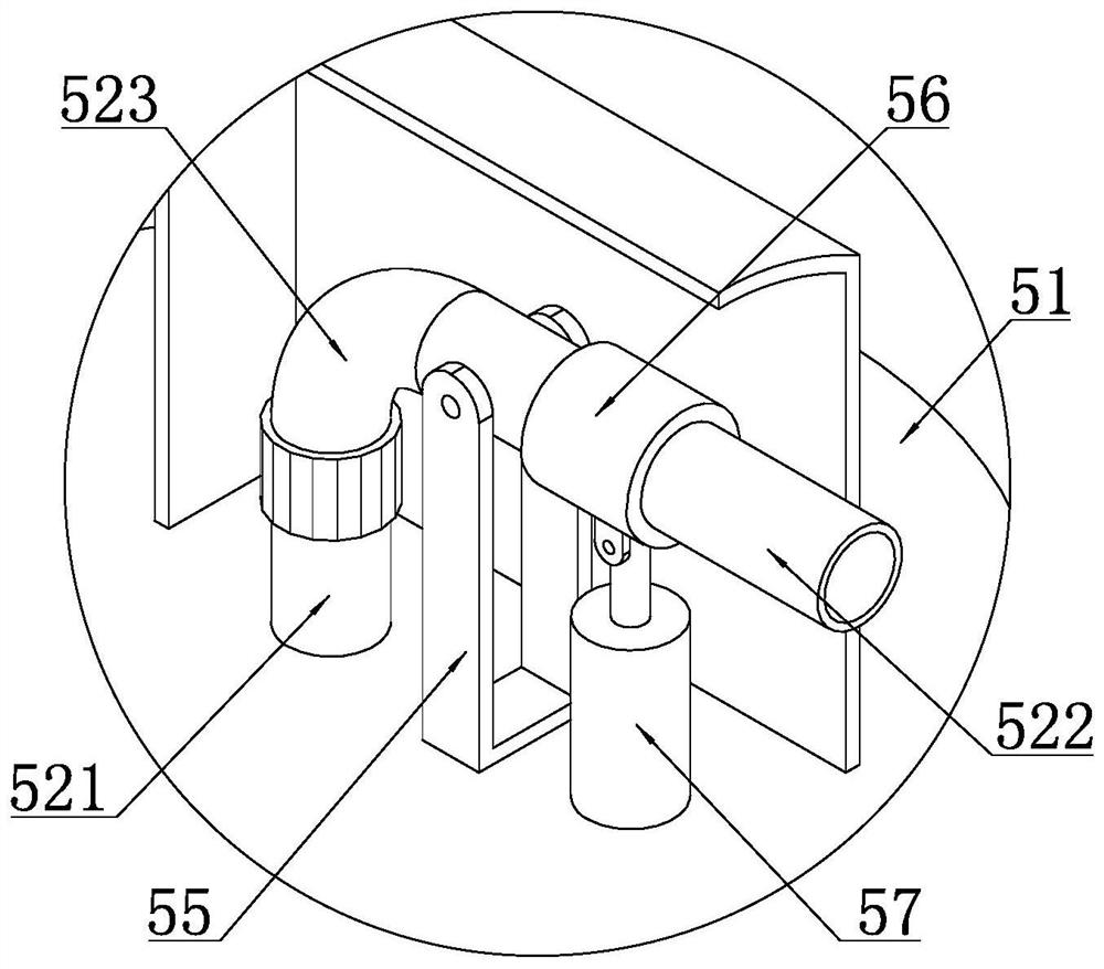
[0055] Such as figure 1 , figure 2 and Figure 4 As shown, a multi-station fusion type substation multi-functional fire fighting equipment includes a support box 1 with a front opening, the support box 1 is a cuboid or cube structure, and the front opening of the support box 1 A door 11 is provided for closing the opening. A guide seat 2 is arranged on the top of the support box 1, and the guide seat 2 is provided with a guide hole passing through the guide seat 2 in the vertical direction, and the lower end of the guide seat 2 is connected to the support box. The upper side wall of the body 1 is fixedly connected.
[0056] Such as Figure 4 As shown, a turntable 3 is arranged in the guide hole of the guide seat 2 , and the turntable 3 is rotatably connected to the upper side wall of the support box 1 . The support box 1 is provided with a first motor 4 , and the power output shaft of the first motor 4 is fixedly connected with the turntable 3 .
[0057] As a specific i...
Embodiment 2
[0083] The turntable 3 includes a circular supporting plate 31, a rotating shaft is coaxially arranged on the lower side of the supporting plate 31, and the lower end of the rotating shaft passes through the upper side wall of the supporting box 1 and extends to the The inside of the supporting box 1, and the rotating shaft is rotatably connected with the upper side wall of the supporting box 1 through a bearing assembly. The power output shaft of the first motor 4 is fixedly connected with the lower end of the rotating shaft through a coupling.
[0084] Preferably, the rotating shaft is rotationally connected with the upper side wall of the supporting box 1 through a thrust ball bearing. A circular groove 12 is arranged on the upper side wall of the supporting box 1 , and a through hole 121 vertically penetrating through the upper side wall of the supporting box 1 is arranged on the bottom surface of the groove 12 . The lower end of the rotating shaft extends to the inside o...
Embodiment 3
[0087] The inner end of the driving arm 66 is directly hinged to the support arm 64 through a hinge shaft, and the support arm 64 is provided with a plurality of hinge holes matched with the hinge shaft, preferably, multiple The two hinge holes are evenly distributed along the length direction of the support arm 64. All the other structures are the same as in Embodiment 1.
PUM
 Abstract
Description
Claims
Application Information
 - R&D
- Intellectual Property
- Life Sciences
- Materials
- Tech Scout
- Unparalleled Data Quality
- Higher Quality Content
- 60% Fewer Hallucinations
Browse by: Latest US Patents, China's latest patents, Technical Efficacy Thesaurus, Application Domain, Technology Topic, Popular Technical Reports.
© 2025 PatSnap. All rights reserved.Legal|Privacy policy|Modern Slavery Act Transparency Statement|Sitemap|About US| Contact US: help@patsnap.com


