
Waste gas multi-filtering equipment

A technology of multiple filtration and equipment, which is applied in the direction of dispersed particle filtration, separation method, and dispersed particle separation, etc., which can solve the problems of environmental protection equipment catalyst pollution, affecting the health of staff, affecting the filtering effect and service life of equipment, etc.

Inactive Publication Date: 2021-07-06
姜年松
View PDF2 Cites 0 Cited by
  • Summary
  • Abstract
  • Description
  • Claims
  • Application Information

AI Technical Summary

Problems solved by technology

[0003] Whether it is coal-fired flue gas desulfurization, denitrification and mercury removal, waste incineration, cement burning, waste gas generated in various industrial kilns and industrial production, combustion of biomass fuel, solid particles in various waste gases containing VOCS, Dirt such as aerosol, oil, paint residue and salt will cause serious pollution to the environmental protection equipment and corresponding catalysts for waste gas treatment, thus affecting the treatment efficiency of environmental protection equipment
[0004] In order to solve this problem, the exhaust gas must be pretreated. When the existing technology filters the exhaust gas, the sealing of the equipment itself is not strong, which is easy to cause exhaust gas leakage, pollute the working environment, and affect the health of the staff. In the prior art, the filter Most of them use the method of filtering all large particles of pollutants at one time, which is very easy to block the leaks, affecting the filtering effect and service life of the equipment, and the existing technology needs to stop maintenance when cleaning the filter screen, which reduces the efficiency of waste gas treatment

Method used


Image

  • Waste gas multi-filtering equipment
  • Waste gas multi-filtering equipment
  • Waste gas multi-filtering equipment

Examples


Embodiment Construction

[0045] The following description serves to disclose the present invention to enable those skilled in the art to carry out the present invention. The preferred embodiments described below are only examples, and those skilled in the art can devise other obvious variations.

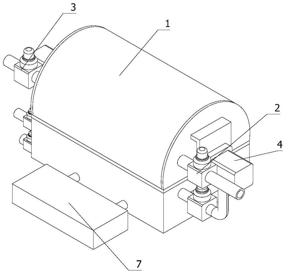
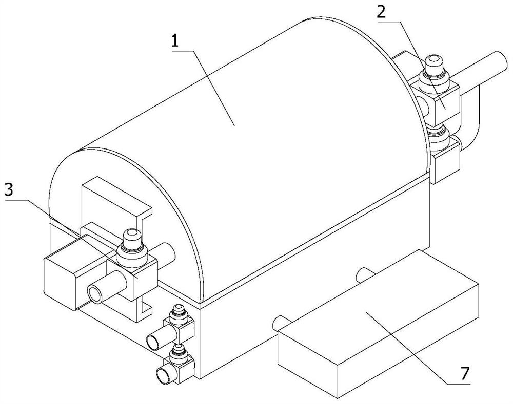
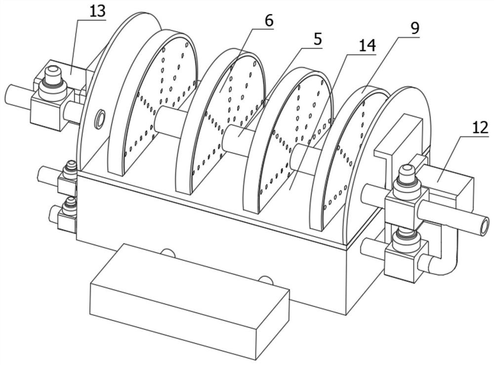
[0046] refer to Figure 1-Figure 15 A multiple filter equipment for exhaust gas is shown:

[0047] Including the waste gas treatment bin 1, the intake end 2 and the exhaust end 3, the middle part of the inside of the waste gas treatment bin 1 is horizontally provided with a partition 14, and the partition 14 divides the internal space of the waste gas treatment bin 1 into an upper bin body 15 and a lower bin body. The bin body 16, the partition 14 is provided with a perforation 17;

[0048] The exhaust gas treatment chamber 1 is provided with multiple filter mechanisms 4, the multiple filter mechanisms 4 are provided with a rotating shaft 5 extending from the intake end 2 to the exhaust end 3 and several fil...


PUM


Abstract

The invention relates to the technical field of environmental protection equipment, in particular to waste gas multi-filtering equipment which comprises a waste gas treatment bin, a gas inlet end and a gas outlet end. A multi-filtering mechanism is arranged in the waste gas treatment bin and is provided with a rotating shaft extending from the gas inlet end to the gas outlet end and filtering discs mounted on the rotating shaft; and the internal space of the upper bin body is divided into a plurality of independent filtering spaces by the filtering discs. Large-particle impurities and colloidal substances in waste gas can be efficiently filtered out, when the air pressure of each filtering space is too large, the pressure of each air filtering space can be relieved through automatic deformation of the filtering disc, and the waste gas filtering efficiency and normal operation of the whole equipment are guaranteed.

Description

technical field [0001] The invention relates to the technical field of environmental protection equipment, in particular to a multiple filtering equipment for waste gas. Background technique [0002] Waste gas pollution control is one of the main areas of environmental protection. Volatile organic pollutants (VOCS) are one of the main pollution factors that produce smog, seriously affecting human health and greatly affecting people's quality of life. At present, the pollution of VOCS to the environment has been widely concerned. [0003] Whether it is coal-fired flue gas desulfurization, denitrification and mercury removal, waste incineration, cement burning, waste gas generated in various industrial kilns and industrial production, combustion of biomass fuel, solid particles in various waste gases containing VOCS, Dirt such as aerosol, oil, paint residue and salt will cause serious pollution to environmental protection equipment and corresponding catalysts for waste gas tr...

Claims


Application Information

Patent Timeline
Patent Type & Authority Applications(China)
IPC IPC(8): B01D46/12B01D46/00
CPCB01D46/12B01D46/762
Inventor 姜年松
Owner 姜年松
Learn More