
Encapsulating device for gradient sensor waterproof cover

A gradient sensor and waterproof cover technology, applied in the direction of the measuring device shell, etc., can solve the problems that affect the efficiency of potting operations, easy to generate air bubbles, volume expansion, etc.

Active Publication Date: 2021-07-06
YANKUANG GRP CO LTD +1
View PDF6 Cites 1 Cited by
  • Summary
  • Abstract
  • Description
  • Claims
  • Application Information

AI Technical Summary

Problems solved by technology

[0004] However, when the existing gradient sensor waterproof cover is being potted, it is inconvenient to feed the workpiece, which affects the work efficiency of the potting operation, and manual feeding also increases the labor cost.
In addition, when the waterproof cover of the gradient sensor is in the potting operation, air bubbles are likely to be generated in the glue, which will cause the volume expansion of the glue after curing, and cause damage to the potted electronic components.

Method used


Image

  • Encapsulating device for gradient sensor waterproof cover
  • Encapsulating device for gradient sensor waterproof cover
  • Encapsulating device for gradient sensor waterproof cover

Examples


Embodiment 1

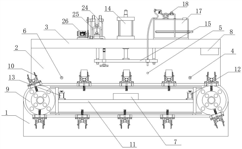
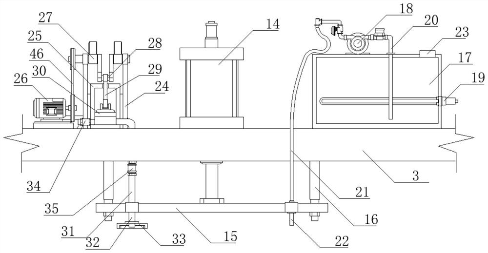
[0035]A potting device for a gradient sensor waterproof cover, comprising a fixed seat 1, the upper end of the fixed seat 1 is fixedly connected with a frame 2, the fixed seat 1 is provided with a feeding assembly, the upper end of the frame 2 is fixedly connected with a top plate 3, and the top plate 3 The lower end is provided with a lifting mechanism, and the lifting mechanism is connected to the connection end of the potting assembly and the vacuum defoaming assembly. The frame 2 is also provided with a discharging sensor 4, a potting sensor 5 and a retrieving sensor 6, and the discharging sensor 4 and The feeding sensor 6 is electrically connected to the feeding electric control box 7, the feeding electric control box 7 is connected to the feeding assembly, the potting sensor 5 is electrically connected to the potting electric control box 8, and the potting electric control box 8 is connected to the lifting mechanism and the potting assembly and vacuum defoaming components...

Embodiment 2

[0042] A potting device for a gradient sensor waterproof cover, specifically including the following operation methods:

[0043] S1. Start the machine through the feeding electric control box 7 and the potting electric control box 8;

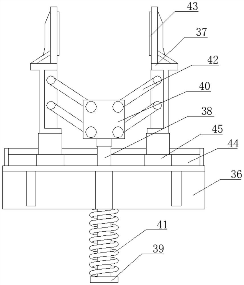
[0044] S2. The chain conveyor belt 9 drives each clamping fixture 10 to move. When a clamping fixture 10 enters the position of the discharging sensor 6, the feeding electric control box 7 receives the signal and controls the solenoid valve of the discharging cylinder 12 to open, and the discharging The piston cylinder of the air cylinder 12 pushes the limit block 39 of the clamping fixture 10, the pressure spring 41 shrinks under force, the sliding rod 38 drives the connecting piece 40 to rise, and the connecting piece 40 drives the two clamping pieces 37 through the connecting rods 29 on both sides. Open, after the workpiece is put into the workpiece by the staff or the external discharging device, the piston rod of the discharging cylinder 12...


PUM


Abstract

The invention discloses an encapsulating device for a gradient sensor waterproof cover. The device comprises a fixed seat, the upper end of the fixed seat is fixedly connected with a rack, the fixed seat is provided with a feeding assembly, the upper end of the rack is fixedly connected with a top plate, the lower end of the top plate is provided with a lifting mechanism, and the lifting mechanism is connected with the connecting end of an encapsulating assembly and a vacuum defoaming assembly. The rack is further provided with a discharging sensor, a encapsulating sensor and a material taking sensor, the discharging sensor and the material taking sensor are electrically connected with a feeding electric control box, the feeding electric control box is connected with the feeding assembly, the encapsulating sensor is electrically connected with an encapsulating electric control box, and the encapsulating electric control box is connected with a lifting mechanism, the encapsulating assembly and the vacuum defoaming assembly; and the lifting mechanism is arranged to be connected with the encapsulating assembly and the vacuum defoaming assembly, the encapsulating assembly and the vacuum defoaming assembly can be driven to be in butt joint with the two workpieces at the same time, therefore, the two workpieces can be subjected to the encapsulating process and the defoaming process at the same time, the working efficiency is improved, and the yield can be increased easily.

Description

technical field [0001] The invention relates to the technical field of potting equipment, in particular to a potting device for a gradient sensor waterproof cover. Background technique [0002] In the process of production and processing, the gradient sensor waterproof cover needs to be potted with glue. Potting is to mechanically or manually pour a liquid compound into a device equipped with electronic components and circuits, and solidify it into a thermosetting polymer insulating material with excellent performance under normal temperature or heating conditions. [0003] Its function is to strengthen the integrity of electronic devices, improve the resistance to external shocks and vibrations; improve the insulation between internal components and lines, which is conducive to the miniaturization and lightweight of devices; avoid direct exposure of components and lines, and improve the waterproof and moisture-proof of devices Performance, and improve the use of performanc...

Claims


Application Information

Patent Timeline
Patent Type & Authority Applications(China)
IPC IPC(8): G01D11/26
CPCG01D11/26
Inventor 张元刚亓玉浩张钺冯建王永建王彬
Owner YANKUANG GRP CO LTD
Learn More