Three-dimensional cross-interface measurement system

A measurement system, cross-interface technology, applied in the field of optical measurement, can solve problems such as projection distortion

Active Publication Date: 2021-07-06
BEIJING INSTITUTE OF TECHNOLOGYGY
View PDF8 Cites 5 Cited by
  • Summary
  • Abstract
  • Description
  • Claims
  • Application Information

AI Technical Summary

Problems solved by technology

Under this condition, due to the existence of quartz glass, the light will be continuously refracted on the inner and outer wall...

Method used


Image

  • Three-dimensional cross-interface measurement system
  • Three-dimensional cross-interface measurement system
  • Three-dimensional cross-interface measurement system

Examples


Embodiment Construction

[0036] In order to enable those skilled in the art to better understand the solutions of the present application, the technical solutions in the embodiments of the present application will be clearly and completely described below in conjunction with the drawings in the embodiments of the present application.

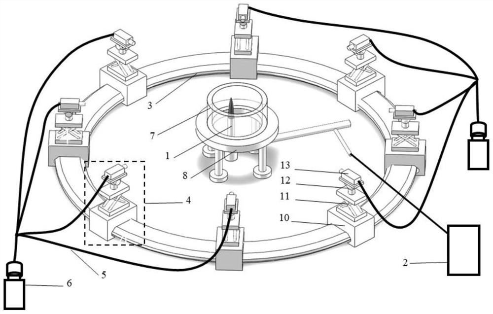
[0037] In this embodiment, taking the signal generator 1 as a burner as an example, the process of transmitting the internal signal of the optical engine to the outside is simulated, and the three-dimensional cross-interface measurement system provided by the present invention is described in detail.

[0038] see figure 1 , is a schematic diagram of the overall structure of a three-dimensional cross-interface measurement system according to an embodiment of the present invention. The three-dimensional cross-interface measurement system according to an embodiment of the present invention includes a circular track 3, a lens assembly 4, an optical fiber 5, a high-speed came...


PUM


Abstract

The invention provides a three-dimensional cross-interface measurement system, which comprises a signal generator, a circular track, a transparent cylinder sleeve, a support and more than two imaging structural members, wherein each imaging structural member comprises a camera and a plurality of lens assemblies. Cross-interface propagation of optical signals such as flame signals is realized by arranging a transparent cylinder sleeve outside an optical signal generator, a plurality of lens assemblies are arranged on a circular track, and the optical signals are propagated to a camera from the lens assemblies, so that two-dimensional projections of the optical signals in different observation directions are obtained. Therefore, a transparent window of the optical engine is replaced by the transparent cylinder sleeve, an internal optical signal is refracted, an optical path propagation path of the optical signal in the optical engine can be simulated, and then the refraction condition of the internal signal of the optical engine when the internal signal passes through the inner wall and the outer wall of the transparent window in the outward transmission process can be simulated; and an experimental method is provided for solving the cross-interface measurement problem.

Description

technical field [0001] The invention belongs to the field of optical measurement, in particular to a three-dimensional cross-interface measurement system. Background technique [0002] With the rapid development of high-speed cameras, lasers, and numerical algorithms, three-dimensional optical diagnosis with temporal and spatial resolution capabilities has become possible. [0003] Currently, optical measurement technology is widely used in flow and combustion fields. Currently commonly used research methods such as tomographic PIV method, laser-induced fluorescence method, phase Doppler method, etc. are inseparable from the signal acquisition of the research area by the imaging sensor, but the current research is basically aimed at the research of the open area, but In practice, some combustion processes occur in a confined space, for example, the spray and combustion process of an internal combustion engine occurs inside the cylinder, and it is difficult for ordinary sens...

Claims


Application Information

Patent Timeline
IPC IPC(8): G01M15/04G01M9/00
CPCG01M15/04G01M9/00
Inventor 伍岳吴海丰龚步高
Owner BEIJING INSTITUTE OF TECHNOLOGYGY
Why Eureka
Try Eureka