3s loose coupling transformer for wireless power transmission and its parameter determination method

A technology of wireless power transmission and loosely coupled transformers, applied in transformer/inductor components, transformer/inductor coils/windings/connections, circuits, etc., can solve problems such as poor anti-offset performance

Active Publication Date: 2022-03-25
HARBIN INST OF TECH
View PDF0 Cites 0 Cited by
  • Summary
  • Abstract
  • Description
  • Claims
  • Application Information

AI Technical Summary

Problems solved by technology

[0005] The purpose of the present invention is to solve the problem of poor anti-offset performance of the magnetic field direction in the coupling mechanism, and propose a 3S loosely coupled transformer for wireless power transmission and a parameter determination method

Method used


Image

  • 3s loose coupling transformer for wireless power transmission and its parameter determination method
  • 3s loose coupling transformer for wireless power transmission and its parameter determination method
  • 3s loose coupling transformer for wireless power transmission and its parameter determination method

Examples


specific Embodiment approach 1

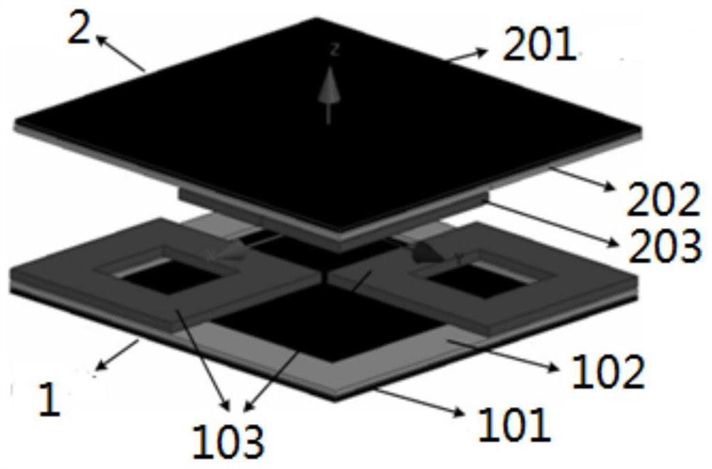
[0037] Specific implementation mode one: the following combination figure 1 This embodiment is described. A 3S (three square) loosely coupled transformer for wireless power transmission described in this embodiment includes a primary side coupling mechanism 1 and a secondary side coupling mechanism 2;

[0038] The primary side coupling mechanism 1 and the secondary side coupling mechanism 2 are arranged oppositely; and the primary side coupling mechanism 1 is located on the lower side of the secondary side coupling mechanism 2;

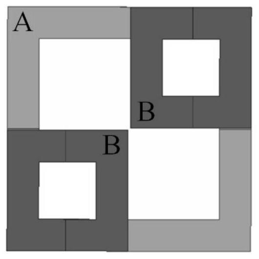
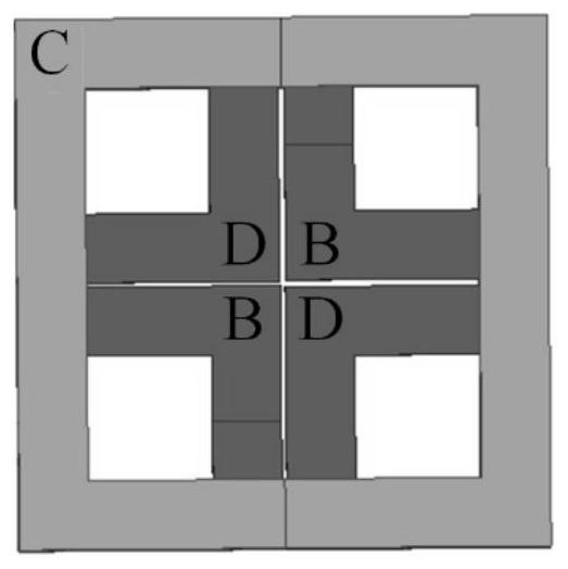
[0039] The primary-side coupling mechanism 1 includes a primary-side ferrite core 101, a coil A102 and two coils B103. The coil A102 is closely arranged along the side of the ferrite and wound in a rectangular ring, and the coil A102 is pasted with ferrite. The upper surface of the body magnetic core; the two coils B103 are independently wound into a rectangular ring, the two coils B103 are attached to the two opposite corners of the coil A102, and th...


PUM


Abstract

A 3S loosely coupled transformer for wireless power transmission and a parameter determination method belong to the technical field of wireless power transmission, in particular to a loosely coupled transformer. The primary side coupling mechanism and the secondary side coupling mechanism are arranged oppositely; and the primary side coupling mechanism is located on the lower side of the secondary side coupling mechanism; the primary side coupling mechanism comprises a primary side ferrite core, a coil A and two coils B, the said The upper surface of the ferrite core is attached to the coil A; Set the lower surface of the ferrite core; the two coils D are independently wound into rectangular rings, the two coils D are attached to two opposite corners of the coil C, and the two coils B and the two coils D are arranged alternately. The present invention is suitable for voltage transformation and regulation.

Description

technical field [0001] The invention belongs to the technical field of wireless power transmission, and in particular relates to a loose coupling transformer. Background technique [0002] When wired power transmission supplies power to multiple devices, there are problems of messy winding and unsightly appearance; when powering underground equipment, electric sparks between contacts are likely to cause dust explosion accidents; when powering underwater equipment, electric leakage accidents are likely to occur; When powering implanted medical equipment, there are problems such as susceptibility to infection and inconvenience; when slip ring power transmission is powering rotating equipment, there are problems such as large mechanical wear and short life. The above shortcomings limit the application of contact power supply in these fields. [0003] Wireless Power Transfer (WPT) technology completes energy transmission through different media such as space magnetic fields, sp...

Claims


Application Information

Patent Timeline
Patent Type & Authority Patents(China)
IPC IPC(8): H01F27/28H01F27/30
CPCH01F27/28H01F27/306
Inventor 姚友素曾明袁悦王懿杰刘晓胜徐殿国
Owner HARBIN INST OF TECH
Why Eureka
Try Eureka