Multistage piezoelectric energy harvesting device for point-supported floating slab track
A piezoelectric energy harvesting and floating plate technology, which is applied in the direction of piezoelectric effect/electrostrictive or magnetostrictive motors, electrical components, generators/motors, etc., can solve the problem of increasing the supported jacking height of the floating plate , The structural size of the piezoelectric energy harvester is large, and the energy harvesting efficiency is not high.
- Summary
- Abstract
- Description
- Claims
- Application Information
AI Technical Summary
Problems solved by technology
Method used
Image

Examples
Embodiment 1
[0049] The multi-stage piezoelectric energy harvesting device for the point-supported floating plate track of this embodiment includes:
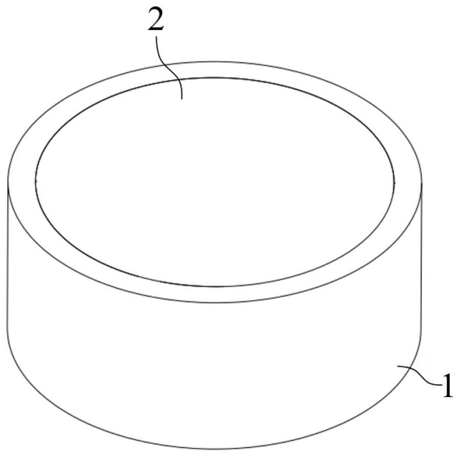
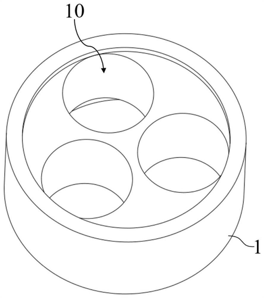
[0050] The shell 1 is a columnar structure, and a columnar energy-harvesting cell cavity 10 is formed in the shell 1 along the axial direction;
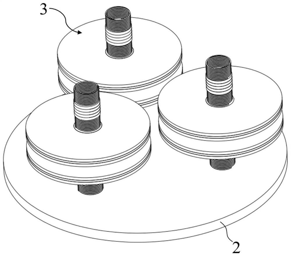
[0051] There are two end plates 2, respectively covering the top surface and the bottom surface of the energy harvesting cell chamber 10;
[0052] An energy-capturing cell 3 placed in the cavity 1 of the energy-capturing cell;
[0053] The energy-harvesting cell 3 includes a spring 30, a stacked energy-harvesting column 31, a spring 30, a mass ball 32, a spring 30, a stacked energy-harvesting column 31, and the spring 30 connected in sequence from top to bottom;
[0054] The surface of the mass ball 32 is sleeved with a curved energy harvesting plate 33 , and the outer wall of the curved energy harvesting plate 33 is fixedly connected with the inner wall of the energy harvesting cell cavity 10 . ...
Embodiment 2
[0061] The multi-stage piezoelectric energy harvesting device for the point-supported floating plate track of this embodiment is further improved on the basis of Embodiment 1. There are two curved energy harvesting plates 33 in the energy harvesting cell 3, which are respectively socketed On the upper half surface and the lower half surface of the mass sphere 32 .
[0062] Such as Figure 4 As shown, this embodiment makes full use of the space of the energy-harvesting cell cavity 10 at the mass sphere 32, where two curved energy-harvesting plates 33 are arranged, and the two curved energy-harvesting plates 33 do not affect each other. When the vibration energy vibrates, the two curved energy-harvesting plates 33 both generate electric energy in the next sentence d31 vibration mode under the influence of the vibration, which increases the total amount of energy captured during the secondary energy-harvesting and improves the energy-harvesting efficiency.
Embodiment 3
[0064] The multi-stage piezoelectric energy harvesting device for the point-supported floating plate track of this embodiment is further improved on the basis of Embodiment 2. The stacked energy harvesting columns 31 include:
[0065] Electrode one 310, which is a flexible electrode;
[0066] Piezoelectric layer one 311, which is made of piezoelectric material;
[0067] Electrode 1 310 and piezoelectric layer 1 311 are alternately and periodically arranged along the axial direction of the energy harvesting cell cavity 10 , and adjacent electrodes 1 310 and piezoelectric layer 1 311 are closely bonded by epoxy resin.
[0068] The specific structure of the stacked energy harvesting column 31 in this embodiment is as follows Image 6 As shown, along the axial direction from top to bottom are electrode 1 310 , piezoelectric layer 1 311 , electrode 1 310 , piezoelectric layer 1 311 , electrode 1 310 .
[0069] The upper and lower ends of the mass ball 32 along the axial direction...
PUM
 Abstract
Description
Claims
Application Information