Exhaust silencer

A technology of exhaust muffler and muffler, which is applied in the direction of exhaust device, muffler device, machine/engine, etc., and can solve the problems of complex manufacture of resonance tubes, etc.

Inactive Publication Date: 2004-04-14
ANDREAS STIHL AG & CO KG
View PDF1 Cites 3 Cited by
  • Summary
  • Abstract
  • Description
  • Claims
  • Application Information

AI Technical Summary

Problems solved by technology

The manufacture of this resonant tube is more complicated

Method used


Image

  • Exhaust silencer
  • Exhaust silencer
  • Exhaust silencer

Examples


Embodiment Construction

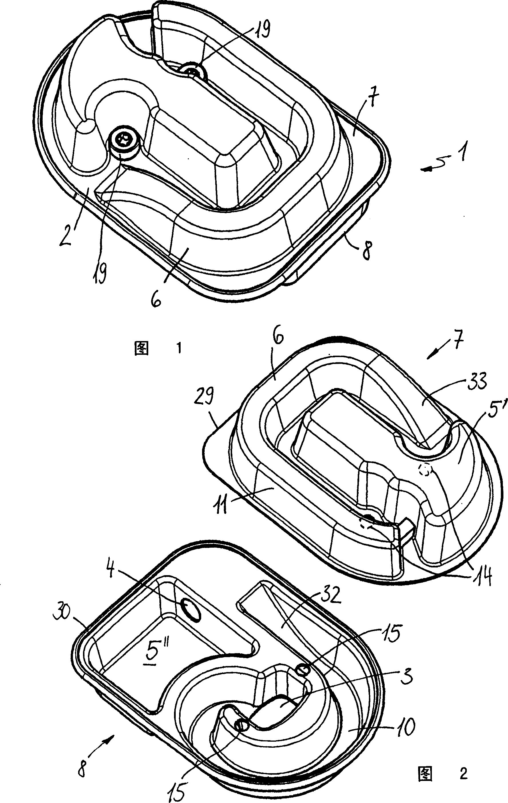
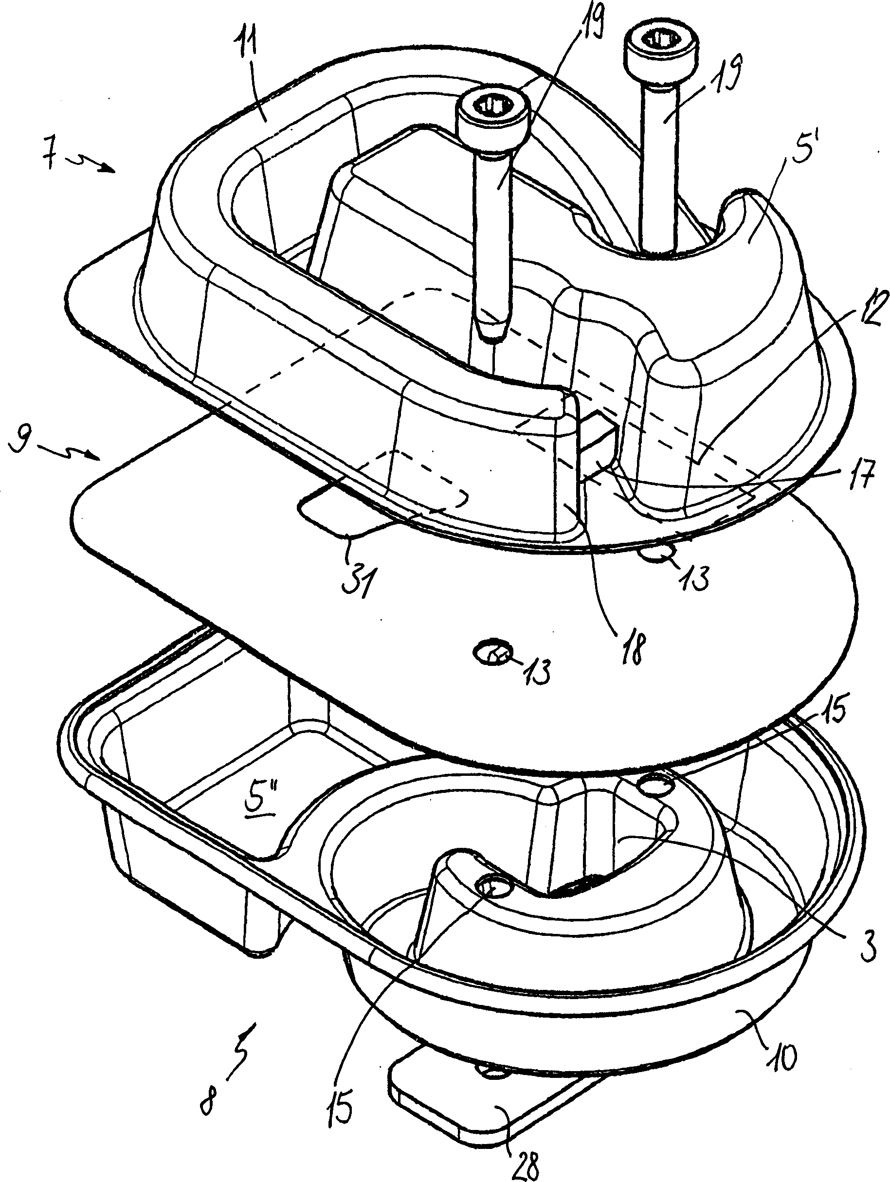
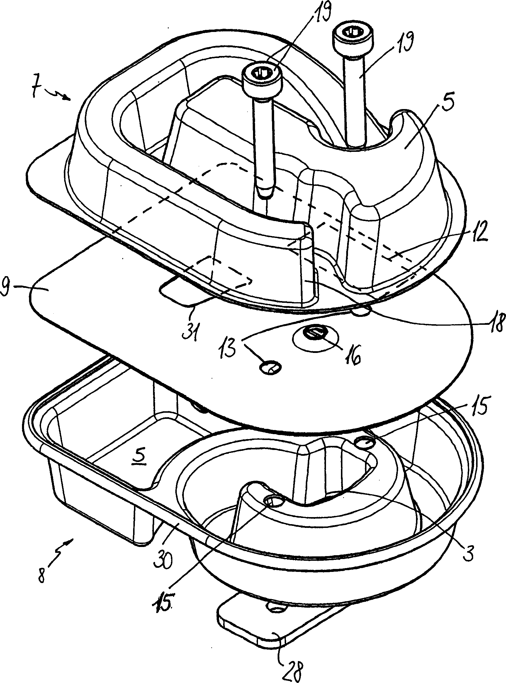
[0018] The exhaust muffler 1 shown in perspective in FIG. 1 has a muffler housing 2 which is formed from an upper half-housing 7 and a lower half-housing 8 . The two half-shells are made of deep-drawn sheet steel, which are connected to each other at the edges shown in FIG. 2 . The edge 30 of the lower half-shell 8 surrounds the edge 29 of the upper half-shell 7 and is crimped around it. In order to fix the exhaust muffler 1 on an internal combustion engine, the upper half shell 7 has two fastening holes 14 and the lower half shell 8 also has two fastening holes 15 . The fastening holes 14 and 15 lie one above the other when the half shells 7 and 8 are fastened. The exhaust muffler 1 can then be fastened to an internal combustion engine with fastening screws 19 protruding through the fastening holes 14 and 15 .

[0019] In the lower housing half 8 pointing toward the internal combustion engine, an inlet opening 3 is provided, the cross section of which reasonably corresponds...


PUM


Abstract

An exhaust-gas muffler includes a muffler housing (2) having an inlet opening (3) and an outlet (4). The exhaust-gas muffler is especially for the internal combustion engine in a portable handheld work apparatus. At least one attenuating space (5, 5', 5'') is configured in the exhaust-gas muffler (1). The exhaust-gas muffler (1) includes at least one resonance pipe (6) to increase power and to reduce the hydrocarbon emissions. The resonance pipe (6) is fluidly connected to the inlet opening (3) and the resonance pipe leads to a backflow of exhaust gases into the combustion chamber (22). For a simple manufacture, it is provided that the exhaust-gas muffler (1) includes lower and upper half shells (8, 7) via which the resonance pipe (6) is at least partially delimited.

Description

technical field [0001] The invention relates to an exhaust muffler, especially for an internal combustion engine in a hand tool, comprising a muffler housing with an inlet opening and an outlet, and in which at least one muffler chamber is arranged , where the exhaust muffler has at least one resonance tube in fluid communication with the inlet opening. Background technique [0002] A two-stroke engine with an exhaust muffler is known from WO 01 / 21941 A1, in which a resonance tube closed on one side is arranged between the outlet of the internal combustion engine and the inlet of the exhaust muffler. The resonance tube is designed as a separate component, which can be arranged helically wound in the sound-absorbing chamber of the silencer. The manufacture of such resonant tubes is relatively complicated. Contents of the invention [0003] The object of the present invention is to provide an exhaust muffler of the above-mentioned type which can be produced relatively simp...

Claims


Application Information

Patent Timeline
Patent Type & Authority Applications(China)
IPC IPC(8): F01N1/02F01N13/18
CPCF01N13/1877F01N2590/06F01N13/1888F01N13/1833F01N1/02
Inventor F·霍歇A·克利梅克
Owner ANDREAS STIHL AG & CO KG
Why Eureka
Try Eureka