
Flexible solar wing with shear fork type unfolding mechanism

A deployment mechanism and flexible technology, applied in the aerospace field, can solve the problems of increasing the assembly time of spacecraft, increasing the complexity of the assembly process and process, unfavorable stand-alone products and mass production of satellites, etc., achieving insensitive assembly gaps, light weight, The effect of reducing quality

Active Publication Date: 2021-07-09
CHINA ACADEMY OF SPACE TECHNOLOGY
View PDF7 Cites 3 Cited by
  • Summary
  • Abstract
  • Description
  • Claims
  • Application Information

AI Technical Summary

Problems solved by technology

[0003] In addition, the traditional solar wing deployment mechanism and the battery array (substrate) are coupled designs. The battery array (substrate) is a part of the deployment mechanism. The solar wing installation must be completed in the unfolded state, which increases the complexity of the final assembly process and process. It increases the assembly time of the spacecraft, which is not conducive to the mass production of stand-alone products and satellites

Method used


Image

  • Flexible solar wing with shear fork type unfolding mechanism
  • Flexible solar wing with shear fork type unfolding mechanism
  • Flexible solar wing with shear fork type unfolding mechanism

Examples


Embodiment Construction

[0028] Exemplary examples of the present disclosure will be described in more detail below with reference to the accompanying drawings, although exemplary embodiments of the present disclosure are shown in the drawings, it should be understood that the present disclosure may be embodied in various forms and should not be constrained by the implementations set forth herein. limited by example. Rather, these embodiments are provided for thorough understanding of the present disclosure, and to fully convey the scope of the present disclosure to those skilled in the art. It should be noted that, in the case of no conflict, the embodiments of the present invention and the features in the embodiments can be combined with each other. The present invention will be described in detail below with reference to the accompanying drawings and examples.

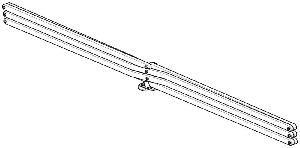
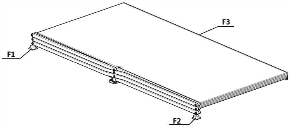
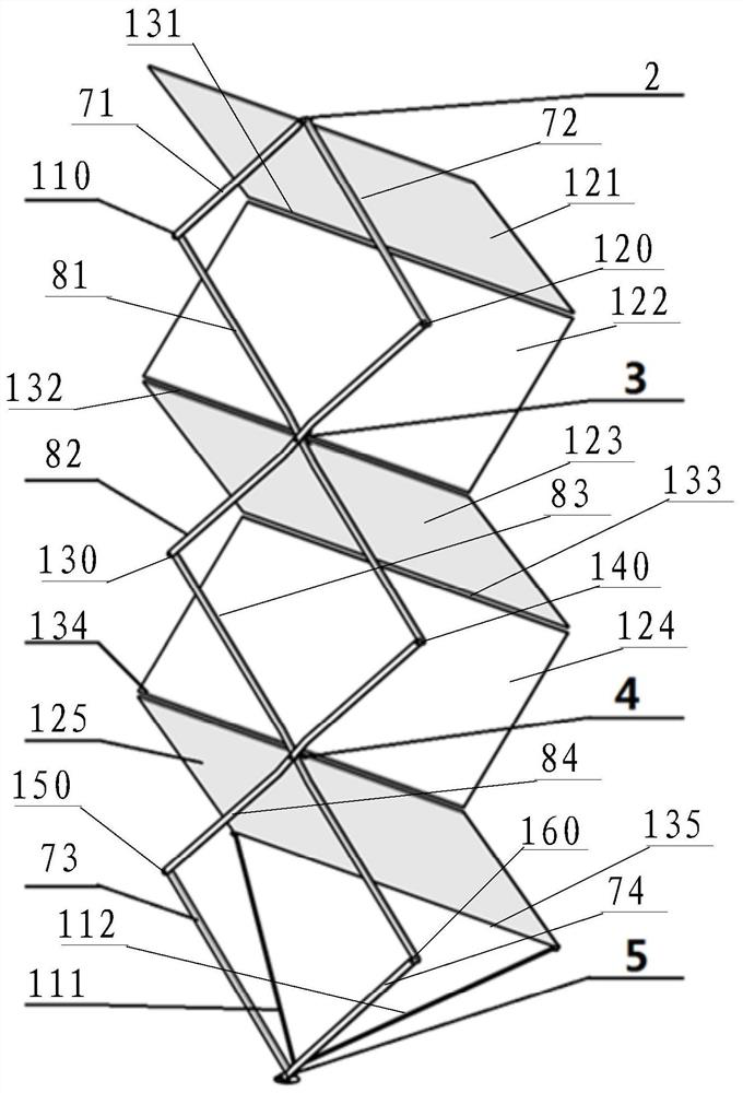
[0029] figure 1 A schematic diagram of the structure of the scissors mechanism provided by the embodiment of the present invention; fi...


PUM


Abstract

The invention discloses a flexible solar wing with a shear fork type unfolding mechanism. The flexible solar wing comprises the shear fork type unfolding mechanism and a flexible solar wing body; and the shear fork type unfolding mechanism is connected with the flexible solar wing body. The flexible solar wing has the advantages of simplicity, light weight and large unfolding and folding ratio.

Description

technical field [0001] The invention belongs to the field of aerospace technology, and in particular relates to a flexible solar wing with a scissor-type deployment mechanism. Background technique [0002] The solar wing is an efficient energy acquisition device for the spacecraft, and the solar wing is the core device for energy conversion, and the number of cells is proportional to the output power of the solar wing. With the increasing power demand of spacecraft, the demand for the number of batteries as the main source of energy is also increasing. However, subject to the constraints of the existing carrying capacity and the envelope space of the fairing, when the weight of the satellite and the envelope in the launch state approach the above constraint boundary, the only way to further increase the volume ratio of the sun’s deployment and retraction and / or reduce the weight of the solar wing , in order to adapt to the increasing power demand of the spacecraft. [0003...

Claims


Application Information

Patent Timeline
Patent Type & Authority Applications(China)
IPC IPC(8): B64G1/22B64G1/44
CPCB64G1/222B64G1/443Y02E10/50
Inventor 李修峰裴胜伟刘绍然韩绍欢王伟梅迪
Owner CHINA ACADEMY OF SPACE TECHNOLOGY
Learn More