Automatic tray placing stock bin

A reel and automatic technology, which is applied in the direction of mechanical conveyors, conveyor objects, transportation and packaging, etc., can solve the problems of small storage of reels, high technical transformation costs, and low work efficiency, and achieve simple structure and technical transformation The effect of low cost and improved production efficiency

Pending Publication Date: 2021-07-09
GOERTEK INC
View PDF6 Cites 4 Cited by
  • Summary
  • Abstract
  • Description
  • Claims
  • Application Information

AI Technical Summary

Problems solved by technology

[0003] The object of the present invention is to provide an automatic plate-swinging silo, aiming at overcoming the problems in the above-mentioned prior art, such as the small number of storage plates, frequent access, inconvenient access, low work efficiency and high cost of technical transformation

Method used


Image

  • Automatic tray placing stock bin
  • Automatic tray placing stock bin
  • Automatic tray placing stock bin

Examples


Embodiment Construction

[0035] In order to make the objectives, technical solutions and advantages of the present invention, the present invention will be described in further detail below with reference to the accompanying drawings and examples. It should be understood that the specific embodiments described herein and the description of the X-direction, Y to the like are merely used to explain the present invention and is not intended to limit the invention.

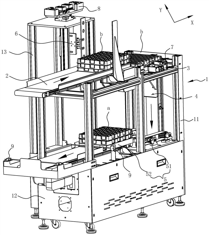
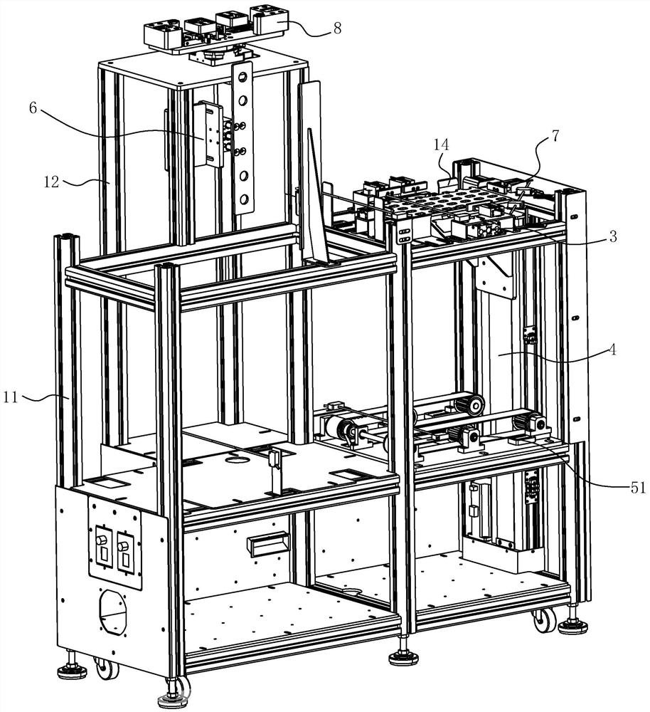
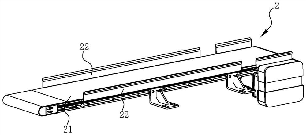
[0036] by Figure 1 to 3 As, the present embodiment discloses an automatic pendulum bin, including the rack 1, and the rack 1 is mainly provided with a space discharge conveying mechanism 2, non-stop panel mechanism 3, full pad handling mechanism. 4 and full material transfer discharge mechanism 5. Wherein, the air disk plate conveying mechanism 2 is used to deliver the air disk B (a button) of the stack pallet to the upper station (in the conveying direction as X). The non-stop ring mechanism 3 is used to carry the robot (not only the robot capab...


PUM


Abstract

The invention discloses an automatic tray placing stock bin. The automatic tray placing stock bin comprises a rack, and an empty tray feeding and conveying mechanism, a non-stop tray placing mechanism, a full tray carrying mechanism and a full tray transferring and discharging mechanism are arranged on the rack; the empty tray feeding and conveying mechanism is used for conveying the stacked empty trays to a feeding station; the non-stop tray placing mechanism is used for bearing single empty trays carried from the feeding station to a product tray placing station, so that tray placing is facilitated; and the non-stop tray placing mechanism is further used for releasing the full trays after the products are placed on the trays; and the full tray carrying mechanism is used for bearing the full trays released one by one by the non-stop tray placing mechanism and integrally carrying the full trays stacked to a preset number to a transferring station; and the full tray transferring and discharging mechanism is used for discharging and conveying the full trays at the transferring station. According to the automatic tray placing stock bin, and the problems that in the prior art, the number of stored trays is small, taking and placing are frequent, taking and placing are inconvenient, the working efficiency is low, and the technical improvement cost is high are solved.

Description

Technical field [0001] The present invention belongs to the field of product pendulum technology, and in particular, the present invention relates to an automatic pendulum bin. Background technique [0002] In the case of plastic, the sealing plate is mainly placed in a universal disc, and can be achieved with a six-axis or four-axis robot. Currently, a common pendulum device is a four-axis (six-axis) and material shadow integrated automation equipment. There is a certain limitations, and the special versatics are universal. The material is not easy to take in the cabinet. Less quantity, it is necessary to manually take the material discharge plate and air disk from the cabinet, and it is necessary to stop waiting for the work efficiency when carrying the full material transfer, and the technical reform cost is higher during different projects. Inventive content [0003] It is an object of the present invention to provide an automatic pendulum silo, which is intended to overcome...

Claims


Application Information

Patent Timeline
Patent Type & Authority Applications(China)
IPC IPC(8): B65G37/00B65G15/00B65G47/74B65G15/12B65G47/24B65G47/26
CPCB65G37/00B65G15/00B65G47/74B65G15/12B65G47/24B65G47/26B65G2201/0258
Inventor 李玉峰冯震冷培猛
Owner GOERTEK INC
Why Eureka
Try Eureka