A swirl flood discharge tunnel with improved water flow

A technology of flood discharge tunnel and flow pattern, which is applied in the directions of hydroelectric power generation, water conservancy project, hydroelectric power station, etc., can solve the problems of unfavorable water flow pattern and large height of water flow in the vortex chamber, and achieves increased thickness, improved water flow pattern, and water surface climbing. The effect of high reduction

Active Publication Date: 2022-07-22
POWERCHINA XIBEI ENG
View PDF3 Cites 0 Cited by
  • Summary
  • Abstract
  • Description
  • Claims
  • Application Information

AI Technical Summary

Problems solved by technology

[0004] In order to overcome the problem that the current rising height of the vortex chamber in the existing vertical shaft swirl flood discharge tunnel is relatively large, which is not conducive to the water flow form, the present invention provides a swirl flood discharge tunnel that improves the flow state of the water flow. Change the flow state to make the water flow into the diversion tunnel regularly, so as to ensure that the inner wall of the diversion tunnel will not be eroded by excessive water flow and improve the service life of the diversion tunnel

Method used


Image

  • A swirl flood discharge tunnel with improved water flow
  • A swirl flood discharge tunnel with improved water flow
  • A swirl flood discharge tunnel with improved water flow

Examples


Embodiment 1

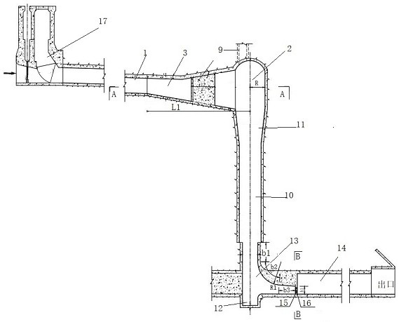
[0024] In order to overcome the problem that the water flow in the vortex chamber has a large rising height, which is unfavorable for the water flow shape in the existing shaft swirl flood discharge tunnel, the present invention provides such as Figure 1-3 As shown in a swirl flood discharge tunnel that improves the flow state of water flow, the present invention changes the flow state through the baffle plate at the end of the connecting section, so that the water flow regularly flows into the diversion hole, so as to ensure that the inner wall of the diversion hole will not be affected by excessive water flow. Erosion improves the service life of the diversion hole.

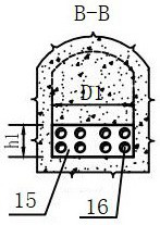
[0025] A swirl flood discharge tunnel for improving water flow, including a water diversion tunnel 1, a transition section 3, a vortex chamber 2, a vertical shaft 10, a stilling pool 12, a water baffle 15 and a diversion tunnel 14. The transition section 3 upstream It is connected with the water diversion tunn...

Embodiment 2

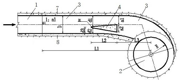
[0029] On the basis of Embodiment 1, in this embodiment, preferably, the transition section 3 is provided with a water dividing wall 4 .

[0030] Preferably, the transition section 3 includes a base plate 5, a side wall 7, a side wall 2 8 and a top arch 6, and the side wall 1 7 and the side wall 2 8 are vertically arranged on the base plate, one outside and one inside. 5 and the top arch 6, the bottom plate 5 is inclined and arranged, the side wall 1 7 is arranged on the side away from the vortex chamber 2, and the side wall 2 8 is arranged on the side close to the vortex chamber 2, and its height is determined by the side wall of the water diversion tunnel 1. The wall height that transitions to the vortex chamber 2; the side wall 1 7 and the side wall 2 8 respectively include a straight section and an arc section along the water flow direction, the arc section of the side wall 7 is connected with the vortex chamber 2, and the arc section of the side wall 2 8 The section is co...

Embodiment 3

[0048] On the basis of Embodiment 1 or 2, preferably in this embodiment, the thickness of the side wall 1 7 is 50cm; the width D of the bottom plate 5 is 720cm, the slope ratio of the bottom plate 5 is 1:5, and the slope ratio of the slope section of the top arch 6 is 1 : 6. The radius R of the vortex chamber 2 is 630cm, the distance a1 between the backwater surface and the side wall 7 of the transition section 3 is 360cm, the width a2 of the backwater surface is 310cm, the arc radius R1 of the upstream surface is 150cm, and the side wall of the upstream surface is 150cm. The distance between the first 7 is d1 is 440cm, the distance d2 between the side wall 2 and the side wall 2 8 is 230 cm, the distance between the central axis of the upstream surface and the side wall 2 8 is d3 is 240 cm, the bottom plate 5 The distance between the slope point and the center line of the vortex chamber 2 is L1 is 4410cm, the downstream length L2 of the water separation wall 4 is 1000cm, and th...


PUM


Abstract

The invention provides a swirling flood discharge tunnel for improving the flow state of water, comprising a diversion tunnel, a transition section, a vortex chamber, a vertical shaft, a stilling pool, a water baffle and a diversion tunnel, and the upstream of the transition section is connected with the diversion tunnel, The upstream of the water diversion tunnel is connected with a sluice chamber; the downstream of the transition section is connected with the vortex chamber, the lower end of the vortex chamber is connected with the vertical shaft through the vertical shaft connecting section, the stilling pool is located at the bottom end of the vertical shaft, and the vortex chamber is located at the bottom of the vertical shaft. The diameter is larger than the diameter of the shaft, and the diameter of the shaft is larger than the diameter of the stilling pool; the lower part of the shaft is connected with the diversion hole through the connecting section, and one end of the diversion hole is blocked; the water baffle is arranged at the end of the connecting section. In the present invention, the transition section from the water diversion tunnel to the vortex chamber forms a gradient, which can cause an increase in the velocity of the water flow entering the vortex chamber. The invention changes the flow state through the water baffle at the end of the connecting section, so that the water flow regularly flows into the diversion hole, thus ensuring that the inner wall of the diversion hole will not be eroded by excessive water flow, and improving the service life of the diversion hole.

Description

technical field [0001] The invention belongs to the technical field of swirl energy dissipation of water conservancy and hydropower projects, and particularly relates to a swirl flood discharge tunnel for improving the flow state of water. Background technique [0002] During the construction of high rockfill dams, tunnels are generally used for diversion, so it is often necessary to build diversion tunnels with large sections, and the cost of diversion tunnels is often relatively high. The purpose of the multi-purpose hole is to reduce the project cost and solve the difficulty of hub layout. According to the 116 cases of dual-use diversion tunnels collected in the "Compilation of Diversion Tunnels in the World", more than 50% of the diversion tunnels were converted into flood discharge tunnels, and 20% were converted into power diversion tunnels or tailrace tunnels. It is converted into an irrigation hole, a vent hole or other multi-purpose tunnel. In the case of rebuilt ...

Claims


Application Information

Patent Timeline
Patent Type & Authority Patents(China)
IPC IPC(8): E02B9/04E02B8/06
CPCE02B9/04E02B8/06Y02E10/20
Inventor 周恒陆希刘静狄圣杰丁新潮王卫国卫勇
Owner POWERCHINA XIBEI ENG
Why Eureka
Try Eureka