Flexible support integrated equipment for complex roadway

A flexible, roadway technology, used in shaft equipment, tunnels, mining equipment, etc., can solve problems such as uncoordinated support structures, distortions, fractures and damage of metal supports, and achieve the effect of enhancing the stability of surrounding rocks

Active Publication Date: 2021-07-09
ANHUI UNIV OF SCI & TECH
View PDF8 Cites 0 Cited by
  • Summary
  • Abstract
  • Description
  • Claims
  • Application Information

AI Technical Summary

Problems solved by technology

[0003] First, the metal support used in the traditional support technology has an uncoordinated support structure and a single support method, and its high strength and high support force support characteristics prevent the relatively high plasticity in the roadway from being released slowly and effectively. Lead to local stress concentration, local fracture damage or distortion of the metal support, and eventually lead to instability of the surrounding rock
[0004] Second, the roadway roof and side wall rocks in our country often have unevenness and large fluctuations. However, the rigid support beams used in the existing support equipment are difficult to make the anchor net fully fit the uneven roadway surface. As a result, the effective support area of ​​the anchor net is reduced, and the joint support effect of the anchor net and the anchor rod is insufficient.
[0005] Thirdly, the manual net laying and manual anchoring methods currently used in underground mines prolong the interval between the three processes of net laying, support, and anchoring, and the cooperative operation ability between temporary support and permanent support is weak. Further lead to the prolongation of the empty roof time of the roadway, which intensifies the deformation of the surrounding rock

Method used


Image

  • Flexible support integrated equipment for complex roadway
  • Flexible support integrated equipment for complex roadway
  • Flexible support integrated equipment for complex roadway

Examples


Embodiment Construction

[0048] In order to make the technical means, creative features, goals and effects achieved by the present invention easy to understand, the present invention will be further described in detail below in conjunction with the accompanying drawings and specific embodiments. It should be understood that the specific embodiments described here are only used to explain the present invention, not to limit the present invention.

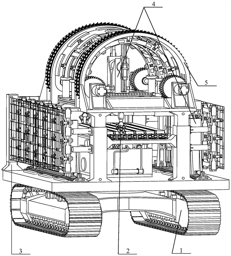
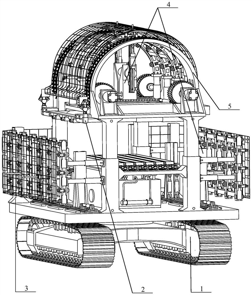
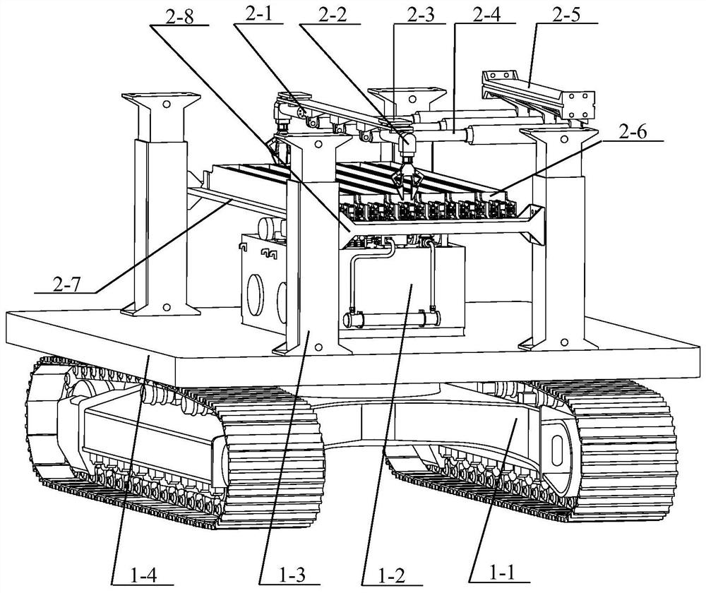
[0049] see figure 1 , figure 2, an integrated flexible support equipment for complex roadways, including walking system 1, roof anchor net access system 2, side side flexible support and net laying system 3, anchor system 4, roof flexible support and net laying system 5 five parts; the roof anchor net access system 2 is installed in the middle of the four sets of hydraulic outriggers 1-3 of the walking system 1 through the anchor net access bottom plate fixed beam 2-8; the side flexible support The net laying system 3 is installed on both sides above the ...


PUM


Abstract

The invention discloses flexible supporting integrated equipment for a complex roadway. The flexible supporting integrated equipment comprises a walking system, a top plate anchor net storing and taking system, a side wall flexible supporting and net laying system, an anchoring system and a top plate flexible supporting and net laying system. Furthermore, an integrated flexible supporting process is adopted, so that the problem that surrounding rock of a complex roadway is not coordinated with a supporting body is solved, and the stability of the surrounding rock is enhanced to the maximum extent; a hydraulic damping type segmented flexible supporting mechanism is used for flexibly supporting the roadway, so that tight attachment of an anchor net and the roadway can be achieved according to the actual deformation degree of the surrounding rock of the roadway; and a top plate double-clamping-hand type automatic net laying device, a side wall double-roller type continuous net laying device and a multiple sets of multi-freedom-degree anchoring systems are adopted, so that collaborative supporting operation is achieved, and full-section automatic net laying and spatial multi-dimensional synchronous supporting functions are achieved.

Description

technical field [0001] The invention belongs to the technical field of roadway support, and in particular relates to flexible support integrated equipment for complex roadways. Background technique [0002] Due to the complex environment of the roadway surrounding rock in our country, there are generally conditions such as soft and broken surrounding rock, separated layers, and abnormal development of cracks in the roadway, and the stability of the roadway is affected by complex external conditions (such as mining influence, soft surrounding rock, high stress, etc. )Greater impact. However, although the traditional support equipment and support technology (such as anchor shotcrete support, rigid U-shaped shed support, etc.) have alleviated the deformation of the surrounding rock to a certain extent by virtue of its high strength and high support force, but There are also obvious flaws: [0003] First, the metal support used in the traditional support technology has an unco...

Claims


Application Information

Patent Timeline
Patent Type & Authority Applications(China)
IPC IPC(8): E21D11/15E21D11/40E21D20/00E21D23/04
CPCE21D11/152E21D11/40E21D20/003E21D23/04
Inventor 赵东洋郭永存王爽杨豚童佳乐杨鹏徐诗虎苏国用
Owner ANHUI UNIV OF SCI & TECH
Why Eureka
Try Eureka