Device and method for testing heat-conducting property of thin film material

A technology for thermal conductivity and thin-film materials, which is applied in the field of thermal conductivity testing devices for thin-film materials, can solve the problems of low thermal conductivity detection accuracy and the like

Active Publication Date: 2021-07-09
NINGBO GRAPHENE INNOVATION CENT CO LTD
View PDF15 Cites 2 Cited by
  • Summary
  • Abstract
  • Description
  • Claims
  • Application Information

AI Technical Summary

Problems solved by technology

[0003] The purpose of this application is to provide a test device and test method for the thermal conductivity of thin film materials, so as to improve the technical problem of low detection accuracy of thermal conductivity of thin film materials

Method used


Image

  • Device and method for testing heat-conducting property of thin film material
  • Device and method for testing heat-conducting property of thin film material
  • Device and method for testing heat-conducting property of thin film material

Examples


Embodiment 1

[0070] Select the polyimide (PI) graphite film that comparative example 1 provides to carry out thermal conductivity test, including:

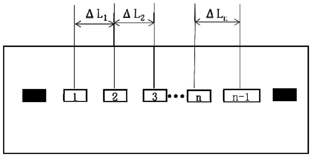
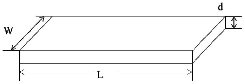
[0071] The PI film is tested by using the thermal conductivity testing device for thin film materials provided by the application, wherein the number of temperature measuring elements is three, and the distance between thermocouple temperature measuring points is ΔL=2cm. The polyimide graphite film has a thickness d of 73 μm and is cut into a rectangle with a width of 1 cm and a length of 10 cm.

[0072] Coat the surface of the heating element, the temperature measuring element and the cooling element with thermally conductive silicone grease, and the thermal conductivity of the thermally conductive silicone grease is 1.5W / (m·K).

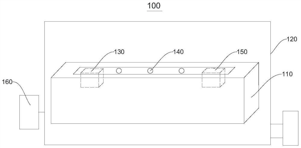
[0073] Please refer to Figure 4 , place the PI film on the test platform. Turn on the vacuum incubator, set the temperature to 25°C, and set the vacuum degree to 1000Pa.

[0074] When the constant temperature fl...

Embodiment 2

[0081] The graphene heat conduction film provided in Comparative Example 2 was selected for thermal conductivity test, and the same test method as in Example 1 was used for testing, the only difference being:

[0082] The thickness of the graphene heat conduction film is d=145μm, cut into a rectangle with a length of 10cm and a width of W=0.5cm. The temperature is set to 800Pa. When the temperature of each point is constant and reaches the steady-state heat flow, the voltage across the heating sheet is U=1.06V, the current I=0.693A, and the electric-thermal conversion rate of the heating sheet is η=80%. The test results in T 1 =37.8°C, T 2 =27.1°C, T 3 =16.8°C, calculated to get ΔT 1 =10.7°C, ΔT 2 =10.3°C, ΔT 平均 =10.5°C, substituted into the formula for calculation, the thermal conductivity λ=771.9W / (m·K).

Embodiment 3

[0086] The graphene heat-conducting film provided in Comparative Example 3 was selected for thermal conductivity testing, and the same test method as in Example 1 was used for testing, the only difference being:

[0087] The thickness of the graphene heat conduction film is d=130μm, cut into a rectangle with a length of 15cm and a width of W=1cm. Set to 500Pa. When the temperature of each point is constant and reaches the steady-state heat flow, the voltage across the heating sheet is U=0.75V, the current I=0.605A, and the electric-thermal conversion rate of the heating sheet is η=80%. The test results in T 1 =33.2°C, T 2 =26.8°C, T 3 =20.6°C, calculated to get ΔT 1 =6.4°C, ΔT 2 =6.3°C, ΔT 平均 =6.2°C, then substitute into the formula to calculate the thermal conductivity λ=886W / (m·K).

[0088] The laser flash method used in the comparative example is a non-steady-state method for testing thermal conductivity. The test principle of this method is that the thin disc sample ...


PUM

PropertyMeasurementUnit
thermal conductivityaaaaaaaaaa

Abstract

The invention provides a device and a method for testing the heat-conducting property of a thin-film material, and relates to the technical field of material property characterization. The thin film material heat-conducting property testing device comprises a testing platform, a heating element, a temperature measuring element and a cooling element. The thin film material heat-conducting property testing device is simple in structure and easy and convenient to operate, a temperature field which does not change along with time is established in a to-be-tested film material on a heat-insulating testing platform through the heating element and the cooling element, the to-be-tested film material reaches a one-dimensional steady-state conduction state, then the temperature gradient of the to-be-tested film material is measured through the temperature measuring element, and then the heat flow and the heat conductivity coefficient are calculated, and the test result precision is high.

Description

technical field [0001] The present application relates to the technical field of material performance characterization, in particular, it relates to a test device and a test method for the thermal conductivity of thin film materials. Background technique [0002] With the advent of the 5G era, more high-frequency, high-power, and thinner devices will emerge. With the emergence of these devices, thin-film heat dissipation materials have been widely used in the field of thermal management of these devices. At present, the laser flash method is mainly used to characterize the heat dissipation performance of thin film materials. This method is expensive to test, cannot test the heat flux of thin film materials, and cannot intuitively characterize the heat flux and heat dissipation performance of films with different thicknesses. There is also a heating method to detect the temperature and heat transfer at different positions on the film. This method has low measurement accuracy ...

Claims


Application Information

Patent Timeline
Patent Type & Authority Applications(China)
IPC IPC(8): G01N25/20G01N25/18
CPCG01N25/20G01N25/18Y02E60/10
Inventor 李妙妙张慧涛刘跃文郭玉芬刘兆平
Owner NINGBO GRAPHENE INNOVATION CENT CO LTD
Why Eureka
Try Eureka