
Light machine module and projection equipment

A technology for opto-mechanical modules and projection equipment, applied in the field of projection, can solve the problems of long distance and long length of opto-mechanical modules, and achieve the effect of shortening the length

Pending Publication Date: 2021-07-09
QINGDAO HISENSE LASER DISPLAY CO LTD
View PDF0 Cites 0 Cited by
  • Summary
  • Abstract
  • Description
  • Claims
  • Application Information

AI Technical Summary

Problems solved by technology

[0004] However, in the above-mentioned beam reduction components, in order to achieve a better beam reduction effect, the distance between the two lenses is usually relatively long, resulting in a longer length of the optical-mechanical module.

Method used


Image

  • Light machine module and projection equipment
  • Light machine module and projection equipment
  • Light machine module and projection equipment

Examples


Embodiment Construction

[0040] In order to make the purpose, technical solution and advantages of the present application clearer, the implementation manners of the present application will be further described in detail below in conjunction with the accompanying drawings.

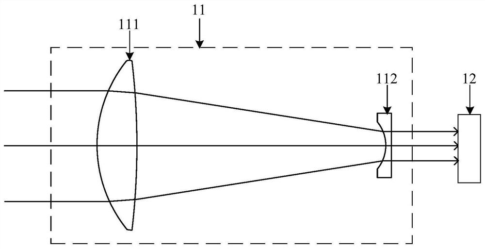
[0041] figure 1 It is a structural schematic diagram of an optomechanical module, which includes a beam shrinker assembly 11 and a light valve 12 .

[0042] Wherein, the beam shrinking assembly 11 includes a first lens 111 and a second lens 112 . Lens 111 can be convex lens, is used for receiving light beam (such as laser beam, and this light beam can be parallel light), and light beam guides lens 112, and second lens 112 can be concave lens, is used for receiving the light beam that first lens 111 derives, and After the light beam is processed into parallel light, it is output to the light valve 12. The light valve 12 may be a liquid crystal light valve, a digital micromirror light valve, or a Micro-Electro-Mechanical System (M...


PUM


Abstract

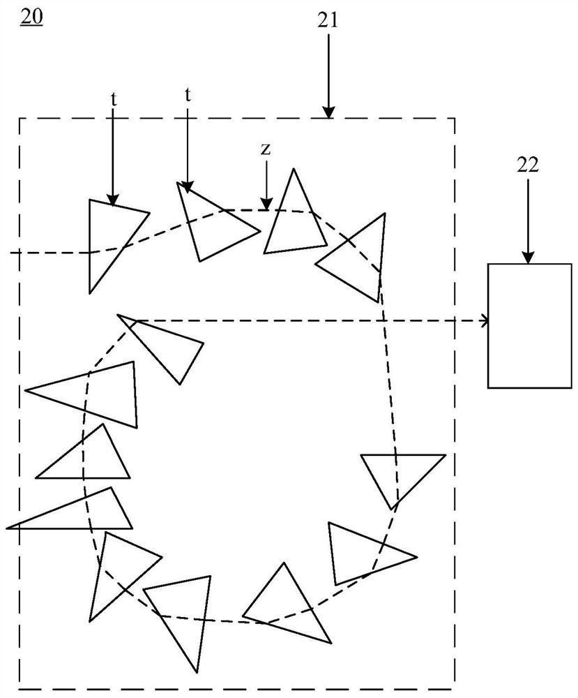
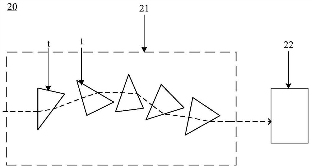
The invention discloses an optical machine module and projection equipment, and belongs to the technical field of projection. The light machine module comprises a prism beam shrinking assembly and a light valve assembly; the prism beam shrinking assembly comprises a plurality of prisms which are sequentially arranged along a light path, in every two adjacent prisms of the prisms, the incident angle of light beams emitted by one prism irradiating the other prism is larger than or equal to 0 degree and smaller than or equal to 20 degrees, and the light paths of the prisms in the prism beam shrinking assembly are in a broken line shape. According to the light machine module comprising the beam shrinking assembly and the light valve assembly, the beam shrinking assembly comprises the multiple prisms, light beams can be shrunk through the multiple prisms, and due to the fact that the light paths of the multiple prisms are in the broken line shape, the overall length of the multiple prisms can be short, so the length of the light machine module is relatively short, the problem that the length of the light machine module is relatively long in the prior art can be solved, and the effect of shortening the length of the light machine module is realized.

Description

technical field [0001] The present application relates to the field of projection technology, in particular to an optical-mechanical module and projection equipment. Background technique [0002] A projection device is a device capable of providing image images, and the projection device may include components such as a light source, an optical-mechanical module, and a lens assembly. The optical engine module is used to adjust the light emitted by the light source and output it to the lens assembly. [0003] An optomechanical module, including a beam shrinking assembly and a light valve assembly, the beam shrinking assembly includes two lenses on the same optical axis, the two lenses are used to shrink the parallel light provided by the light source, and reduce the beam The processed light is output to the lens assembly. [0004] However, in the above-mentioned beam shrinking assembly, in order to achieve a better beam shrinking effect, the distance between the two lenses ...

Claims


Application Information

Patent Timeline
Patent Type & Authority Applications(China)
IPC IPC(8): G03B21/20G03B21/14
CPCG03B21/142G03B21/2033G03B21/208
Inventor 阴亮
Owner QINGDAO HISENSE LASER DISPLAY CO LTD
Learn More