Automatic welding jig for engineering machinery excavating equipment

An automatic welding and excavation equipment technology, applied in metal processing equipment, manufacturing tools, welding equipment, etc., can solve the problems of inaccurate manual assembly size, easy to miss installation parts, unstable welding leg size, etc., to reduce manual welding , avoid part shifting, penetration and forming uniform and controllable effect

Pending Publication Date: 2021-07-13
NANTONG GUOSHENG PRECISION MACHINERY
View PDF5 Cites 0 Cited by
  • Summary
  • Abstract
  • Description
  • Claims
  • Application Information

AI Technical Summary

Problems solved by technology

[0002] The welding of existing engineering excavation parts mostly adopts partial welding, manual welding, which is inefficient, and there is a large welding deformation during the welding process, which requires post-welding plastic correction, manual welding is easy to miss the installation parts, and the size of manual assembly Inaccurate and poor consistency, manual welding is affected by objective factors, unstable parameters, unstable welding leg size, insufficient penetration, and unsightly shape, so a jig is needed to realize the overall welding automation, so as to avoid welding heat Displacement of parts due to deformation

Method used


Image

  • Automatic welding jig for engineering machinery excavating equipment
  • Automatic welding jig for engineering machinery excavating equipment
  • Automatic welding jig for engineering machinery excavating equipment

Examples


Embodiment Construction

[0026] In order to make the object, technical solution and advantages of the present invention clearer, the present invention will be further described in detail below with reference to the accompanying drawings and embodiments. However, it should be understood that the specific embodiments described here are only used to explain the present invention, and are not intended to limit the scope of the present invention.

[0027] Unless otherwise defined, all technical terms and scientific terms used herein have the same meaning as commonly understood by those skilled in the technical field of the present invention, and the terms used in the description of the present invention herein are only to describe specific implementations The purpose of the example is not intended to limit the present invention.

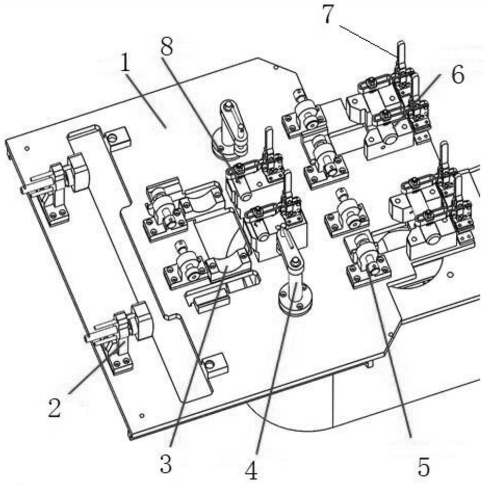
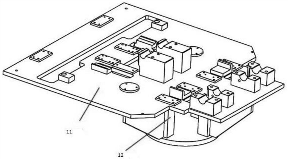
[0028] refer to figure 1 , an automatic welding jig for construction machinery excavation equipment, including a welding base 1, the welding base 1 includes a base plate 11 and ...


PUM


Abstract

The invention discloses an automatic welding jig for engineering machinery excavating equipment, which comprises a welding base, wherein the welding base comprises a bottom plate and a support; a shovel plate pressing device, a supporting tube positioning reference, a supporting arm vertical pressing device, a supporting arm horizontal pressing device, a bearing seat positioning shaft, an oil cylinder lug plate positioning shaft and a vertical pressing quick clamp are arranged on the bottom plate; the shovel plate pressing device comprises a shovel plate base support pushing screw rod, a guide rod and a pressing block; the supporting tube positioning reference is fixed on the welding base; the supporting arm vertical pressing device comprises a support, a cantilever and a pressing screw rod I; the support is fixed on the welding base; the pressing screw rod I is connected with the cantilever; the supporting arm horizontal pressing device comprises a bracket I and a pressing screw rod II; the bracket I is fixed on the welding base; and the pressing screw rod II is connected with the bracket I. According to the jig, overall welding automation can be achieved, the jig can accurately position all parts and is provided with the pressing devices, therefore, part displacement caused by welding thermal deformation can be avoided, and pressing is convenient and fast.

Description

technical field [0001] The invention relates to an automatic welding jig for excavating equipment of engineering machinery, which belongs to the field of engineering machinery. Background technique [0002] The welding of existing engineering excavation parts mostly adopts partial welding, manual welding, which is inefficient, and there is a large welding deformation during the welding process, which requires post-welding plastic correction, manual welding is easy to miss the installation parts, and the size of manual assembly Inaccurate and poor consistency, manual welding is affected by objective factors, unstable parameters, unstable welding leg size, insufficient penetration, and unsightly shape, so a jig is needed to realize the overall welding automation, so as to avoid welding heat Displacement of parts due to deformation. Contents of the invention [0003] Aiming at the problems existing in the above-mentioned prior art, the present invention provides an automatic...

Claims


Application Information

Patent Timeline
Patent Type & Authority Applications(China)
IPC IPC(8): B23K37/00B23K37/04
CPCB23K37/00B23K37/0443
Inventor 张志永闫文忠
Owner NANTONG GUOSHENG PRECISION MACHINERY
Why Eureka
Try Eureka