Automatic wire and steel bar conveying device

A technology for transportation device and steel bar, applied in the field of automatic feeding device for wire rods, can solve the problems of low efficiency, large workload, high labor intensity, etc., and achieve the effects of simple assembly and disassembly, improving work efficiency and reducing labor intensity.

Pending Publication Date: 2021-07-13
CHINA HUAYE GROUP
View PDF4 Cites 0 Cited by
  • Summary
  • Abstract
  • Description
  • Claims
  • Application Information

AI Technical Summary

Problems solved by technology

[0004] In view of the above problems, the purpose of the present invention is to provide an automatic feeding device for wire rods a

Method used


Image

  • Automatic wire and steel bar conveying device
  • Automatic wire and steel bar conveying device

Examples


Example Embodiment

[0027] The present invention provides a wire reinforced automatic transmission device for the aforementioned manual handling wire due to the aforementioned manual handling wire, which provides a problem of high efficiency, low labor intensity.

[0028] A specific embodiment of the present invention will be described in detail below with reference to the accompanying drawings.

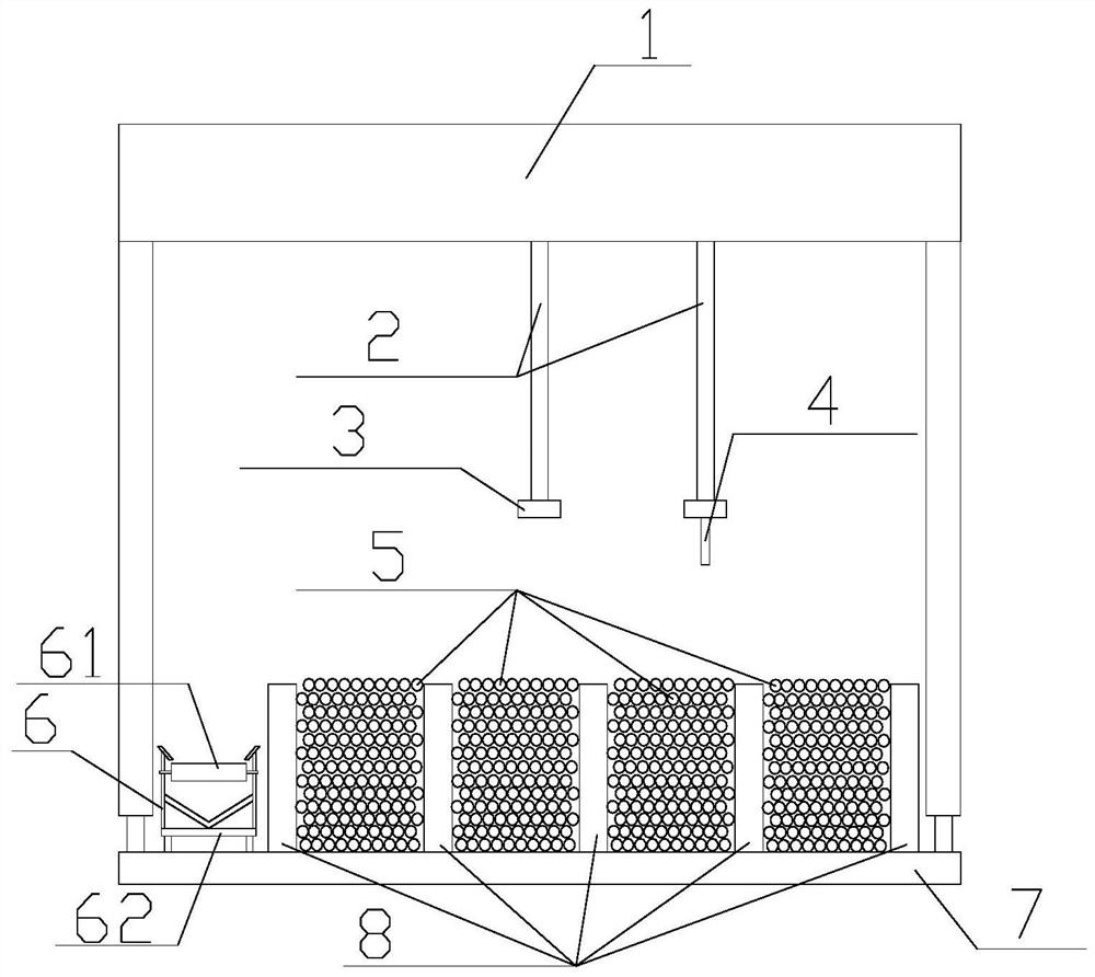
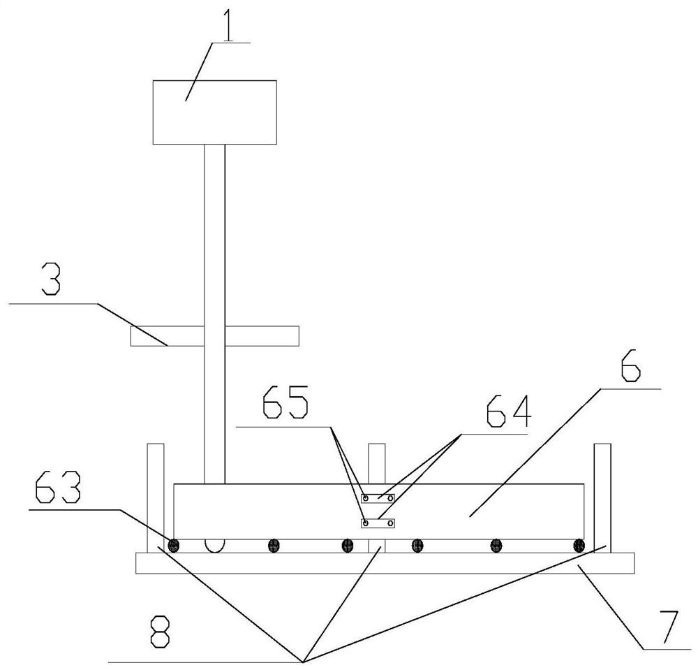
[0029] In order to illustrate the structure of the wire reinforcing light transfer device provided by the present invention, figure 1 with figure 2 The structure of the wire reinforcement automatic transfer device is exemplified from different angles. specifically, figure 1 A cross-sectional structure of a wire reinforcing bar automatic transmission device according to an embodiment of the present invention is shown. figure 2 A side structure of the automatic transfer device of the wire steel bar according to an embodiment of the present invention is shown.

[0030] Such as figure 1 with figure 2 In common,...


PUM


Abstract

The invention discloses an automatic wire and steel bar conveying device. The device comprises a wire conveying device, steel bar classification columns, a gantry crane, a steel wire rope arranged on the gantry crane, electromagnets arranged on the steel wire ropes and hooks; every two rows of steel bar classification columns form a steel bar classification groove, and wire reinforcing steel bars of different specifications are placed in the steel bar classification grooves; the wire reinforcing steel bars are hoisted into the corresponding reinforcing steel bar classification grooves through the steel wire ropes and the hooks; and the wire reinforcing steel bars in the reinforcing steel bar classification grooves are hoisted to the wire transporting device through the steel wire ropes and the electromagnets, and the wire transporting device is used for transporting the wire reinforcing steel bars to a reinforcing steel bar machining area. By means of the device, the problems of large workload, low efficiency, large labor intensity and the like caused by manual wire carrying can be solved.

Description

technical field [0001] The invention relates to the technical field of construction, and more specifically, to an automatic feeding device for wire and steel bars. Background technique [0002] In the main construction of high-rise buildings, the processing volume of steel bars is huge. At present, the processing of wire rod steel bars has been automated, but because the length of a single wire steel bar is 9m or 12m, its length is too long, resulting in no transportation equipment for steel bars. Only manual handling of the wires to the steel bar processing shed is possible, resulting in problems such as heavy workload, low efficiency, and high labor intensity. [0003] In order to solve the above problems, the present invention provides an automatic feeding device for wire rods and steel bars. Contents of the invention [0004] In view of the above problems, the purpose of the present invention is to provide an automatic feeding device for wire rods and steel bars to so...

Claims


Application Information

Patent Timeline
IPC IPC(8): B66C1/14B66C1/06B66C13/08B66C13/00
CPCB66C1/14B66C1/06B66C13/08B66C13/00
Inventor 刘君
Owner CHINA HUAYE GROUP
Why Eureka
Try Eureka