Efficient winding device for optical fiber gyroscope production

A fiber optic gyroscope and winding device technology, which is applied in measuring devices, instruments, transportation and packaging, etc., can solve problems such as wire damage and affect production efficiency, and achieve the effect of reducing tension and improving reliability

Active Publication Date: 2021-07-13
青岛君戎汇通光电科技有限公司
View PDF8 Cites 4 Cited by
  • Summary
  • Abstract
  • Description
  • Claims
  • Application Information

AI Technical Summary

Problems solved by technology

The optical fiber axial arrangement structure in the above-mentioned patent has the following disadvantages: Although it can meet certain production requirements, in the winding process, as the number of winding layers increases, the winding radius must gradually increase, and the pay-off radius It will inevitably decrease gradually, and one will ebb and flow. When the speed of the pay-off motor and the AC servo motor are constant, the wire must be tightened based on the difference in line speed; this will easily cause damage to the wire and affect production efficiency.

Method used


Image

  • Efficient winding device for optical fiber gyroscope production
  • Efficient winding device for optical fiber gyroscope production
  • Efficient winding device for optical fiber gyroscope production

Examples


Embodiment 1

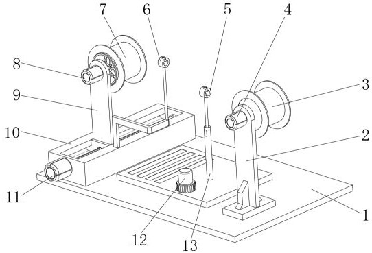
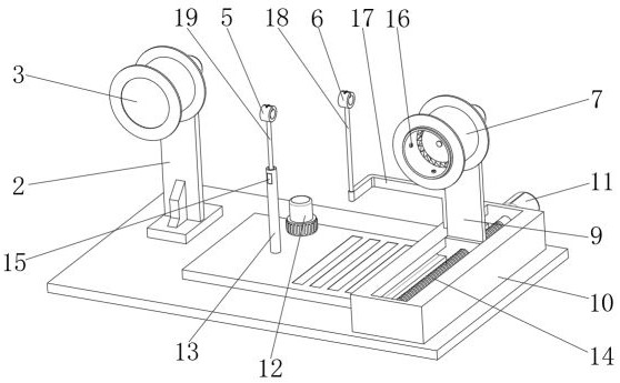
[0033] A high-efficiency winding device for fiber optic gyroscope production, such as Figure 1-6 As shown, it includes a mounting table 1, the outer wall of the top of the mounting table 1 is fixed with a mounting frame 2 by screws, and the outer wall of one side of the mounting frame 2 is fixed with a pay-off motor 4 through screws, and the output end of the pay-off motor 4 is connected to a pay-off motor in rotation. Wheel 3, wire rod is wound on the pay-off wheel 3; the outer wall of the top of the installation table 1 is provided with a translation mechanism, and the movable frame 9 is movably connected in the translation mechanism, and the outer wall of one side of the movable frame 9 is fixed with a winding motor by screws 8. The output end of the winding motor 8 is rotatably connected to a winding main shaft 25, the outer wall of the winding main shaft 25 is integrally provided with a limit ring 24, and the outer wall of the limit ring 24 is slidably connected with two ...

Embodiment 2

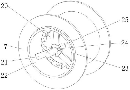
[0043] A high-efficiency winding device for fiber optic gyroscope production, such as Figure 4 As shown, in order to improve the reliability of winding; the present embodiment makes the following improvements on the basis of Embodiment 1: the number of the movable teeth 30 is more than three, and the three movable teeth 30 and the meshing teeth 27 are formed over time. Change staggered mesh structure.

[0044] This embodiment has been proved by many tests, because the movable teeth 30 with a staggered meshing structure are provided, the dislocation rotation between the rotating cylinder 22 and the mounting plate 20 can be made more gentle, so that the tightness of the wire winding process is more even, Thereby improving product quality.


PUM


Abstract

The invention discloses an efficient winding device for optical fiber gyroscope production, and relates to the technical field of optical fiber gyroscope winding devices. To enable the tightness of a wire rod to be conveniently regulated and controlled, the device specifically comprises a mounting table, a mounting frame is arranged on the outer wall of the top of the mounting table, a pay-off motor is arranged on the outer wall of one side of the mounting frame, the output end of the pay-off motor is rotationally connected with a pay-off wheel, and a wire is wound around the pay-off wheel; and a translation mechanism is arranged on the outer wall of the top of the mounting table, and a movable frame is movably connected into the translation mechanism. By arranging the pay-off wheel, a rotating cylinder, an optical fiber ring and other structures, when the acting force reaches a certain degree, the deformation of a movable tooth spring causes a movable tooth to slide into the next meshing tooth, so that a mounting disc rotates by the angle of one meshing tooth relative to the rotating cylinder, the tightening state of a wire is relieved, the borne tension is reduced, the phenomenon that the wire is pulled to be damaged is effectively avoided, the rotating speed of a winding motor and the rotating speed of the pay-off motor do not need to be accurately controlled, and reliability is improved.

Description

technical field [0001] The invention relates to the technical field of fiber optic gyroscope winding devices, in particular to a high-efficiency winding device for fiber optic gyroscope production. Background technique [0002] The fiber optic gyroscope has the advantages of no mechanical moving parts, no warm-up time, insensitive acceleration, wide dynamic range, digital output, and small size; the fiber optic ring of the fiber optic gyroscope is the core of the fiber optic gyroscope; in the production of the fiber optic gyroscope, Winding work is required. The general winding device is composed of a winding part and a wire supply part. During production, the wire supply part supplies the wire, and the winding part winds it on the optical fiber ring. However, in the winding process, as the number of winding layers increases, the winding radius must gradually increase, and the pay-off radius must gradually decrease. When the rotation speed is constant, the wire must be tens...

Claims


Application Information

Patent Timeline
Patent Type & Authority Applications(China)
IPC IPC(8): G01C25/00B65H49/34B65H54/44B65H57/06B65H63/04
CPCG01C25/00B65H49/34B65H54/44B65H57/06B65H63/04
Inventor 刘铭李林杰
Owner 青岛君戎汇通光电科技有限公司
Why Eureka
Try Eureka