Power electrical transformer with good heat dissipation effect

A technology of electric power and heat dissipation effect, which is applied in the field of transformers, can solve the problems of simple structure of heat dissipation and heat dissipation devices, failure to meet heat dissipation requirements, loss and hidden safety hazards, etc., to facilitate disassembly, cleaning and maintenance, improve the effective utilization of resources, and reduce electric energy The effect of using

Pending Publication Date: 2021-07-13
梁国华
View PDF0 Cites 3 Cited by
  • Summary
  • Abstract
  • Description
  • Claims
  • Application Information

AI Technical Summary

Problems solved by technology

Since the box-type transformer installs the transformer inside the box, in order to reduce the volume, the box is often designed as small as possible, resulting in a small space between the transformer and the box. The heat generated by the device will cause aging of the circuit, or even a short circuit of the circuit, resulting in inevitable losses and potential safety hazards
In order to solve this problem, a heat dissipation device is usually installed inside the installation box of the electrical transformer. The existing heat dissipation device has a simple structure and cannot meet the heat dissipation requirements.

Method used


Image

  • Power electrical transformer with good heat dissipation effect
  • Power electrical transformer with good heat dissipation effect
  • Power electrical transformer with good heat dissipation effect

Examples


Embodiment Construction

[0035] In order to enable those skilled in the art to better understand the technical solutions of the present invention, the present invention will be further described in detail below in conjunction with the accompanying drawings.

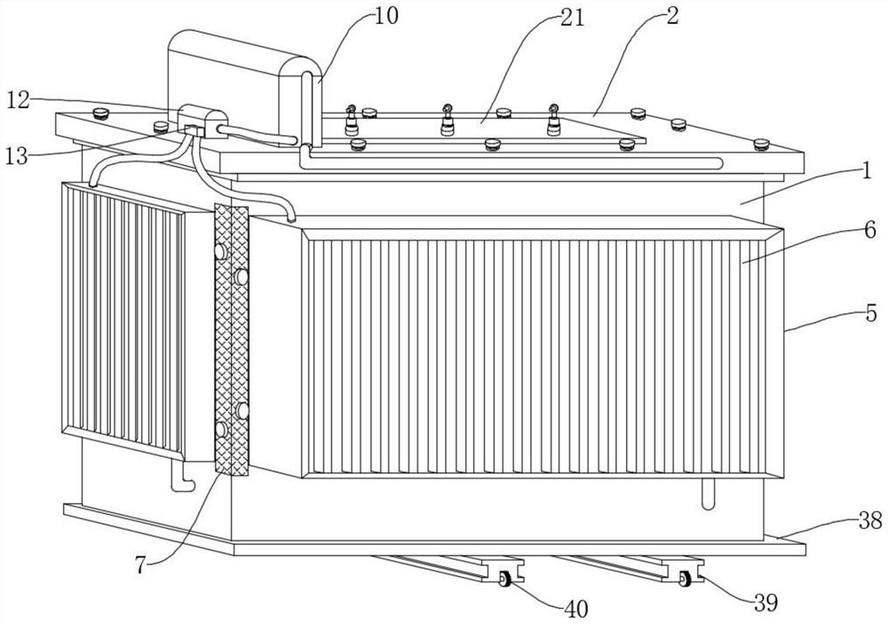
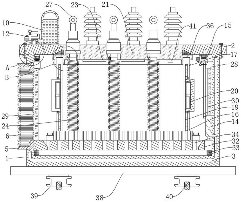
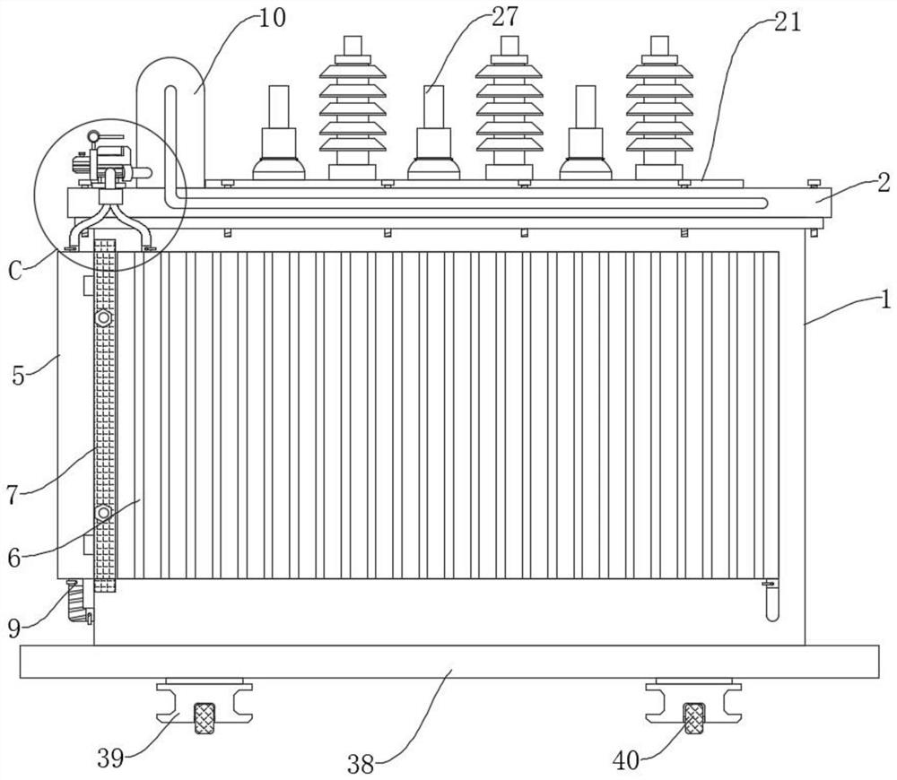
[0036] The present invention provides such as Figure 1-11 A power electrical transformer with good heat dissipation effect is shown, comprising a box body 1, a cover plate 2 is provided on the top of the box body 1, and the box body 1 and the cover plate 2 are fixedly connected by screws, the front side of the box body 1 and the cover plate 2 are fixedly connected. One side of the box is provided with a heat exchange component, and the side wall and the bottom wall of the box body 1 are provided with a heat insulation cavity 3, and a plurality of heat insulation cavities 3 are connected to each other, and the inside of the box body 1 is provided with a transformer function Assemblies, the top of the cover plate 2 is provided with a positioning n...


PUM


Abstract

The invention discloses a power electrical transformer with a good heat dissipation effect, which comprises a box body, a cover plate is arranged at the top of the box body, the box body is fixedly connected with the cover plate through screws, heat exchange assemblies are arranged on the front surface and one side of the box body, heat insulation cavities are formed in the side wall and the bottom wall of the box body, and the multiple heat insulation cavities are communicated with each other. A transformer functional assembly is arranged in the box body. The heat insulation cavity is filled with cooling oil to isolate external heat, the air circulation performance in the box body is high, multiple heat dissipation modes are matched, a reasonable heat dissipation mode is autonomously selected for operation by using an adjusting system according to the real-time temperature and requirements, the heat dissipation efficiency can be maximized, the heat exchange corrugated plates distributed in a snake-shaped stacking mode are combined with the oil passing holes, the superficial area of the heat exchange face is greatly increased, cooling oil is combined for cooling, the heat dissipation efficiency is greatly improved, the device is convenient to install and connect, and the heat exchange assembly can be conveniently detached, cleaned and maintained.

Description

technical field [0001] The invention relates to the technical field of transformers, in particular to a power electric transformer with good heat dissipation effect. Background technique [0002] The transformer is a device that uses the principle of electromagnetic induction to change the AC voltage. The main components are the primary coil, the secondary coil and the iron core (magnetic core). The main functions are: voltage conversion, current conversion, impedance conversion, isolation, voltage stabilization (magnetic saturation transformer), etc. According to the use, it can be divided into: power transformers and special transformers (electric furnace transformers, rectifier transformers, power frequency test transformers, voltage regulators, mining transformers, audio transformers, intermediate frequency transformers, high frequency transformers, impact transformers, instrument transformers, electronic transformers , reactors, transformers, etc.). [0003] The exist...

Claims


Application Information

Patent Timeline
Patent Type & Authority Applications(China)
IPC IPC(8): H01F27/00H01F27/02H01F27/06H01F27/08H01F27/14H01F27/30H01F27/33H01F27/40
CPCH01F27/002H01F27/022H01F27/06H01F27/08H01F27/085H01F27/14H01F27/306H01F27/33H01F27/402H01F2027/404H01F2027/406
Inventor 不公告发明人
Owner 梁国华
Why Eureka
Try Eureka