
Distributor

A technology for distributors and connectors, which is applied in the direction of coupling devices, electrical components, circuits, etc., can solve problems such as unfavorable carrying and installation, skewed pin assembly, troublesome disassembly and replacement, etc., to improve assembly speed and assembly accuracy, and ensure installation Reliability, reliable effect of disassembly and installation

Pending Publication Date: 2021-07-13
苏州丰年科技股份有限公司
View PDF0 Cites 0 Cited by
  • Summary
  • Abstract
  • Description
  • Claims
  • Application Information

AI Technical Summary

Problems solved by technology

[0003] The existing distributors generally have connection ports set on the same side of the device, and the cables have a certain thickness, and in order to facilitate installation, the connection ports are usually arranged in a row. Therefore, the existing distribution Devices are usually bulky and long, which is not conducive to portability and installation, and also increases manufacturing costs
[0004] And in the process of use, some equipment is usually installed at a position higher than the distributor. When the traditional distributor is connected to the equipment, the cable needs to be connected from the lower end of the distributor and then bent upwards and then connected to the higher position. The device is connected, this connection method is convenient, it will lead to inconvenient installation, on the other hand, it will cause damage to the cable if it is used for a long time
[0005] In the traditional distributor, the pins need to be connected to the circuit board one by one. Since the pins are generally small in size, the operator has high technical requirements when assembling the pins, and the accuracy of pin assembly cannot be guaranteed. , there is a situation where the pin assembly is skewed, which leads to a low yield rate of the product and low assembly efficiency
[0006] The traditional distributor generally adopts an integrated design, that is, the distributor is fixed and installed by directly opening a mounting hole on the distributor shell. This installation method is not only inconvenient to install, but also not reliable enough to disassemble and replace. kind of hard

Method used


Image

  • Distributor
  • Distributor
  • Distributor

Examples


Embodiment

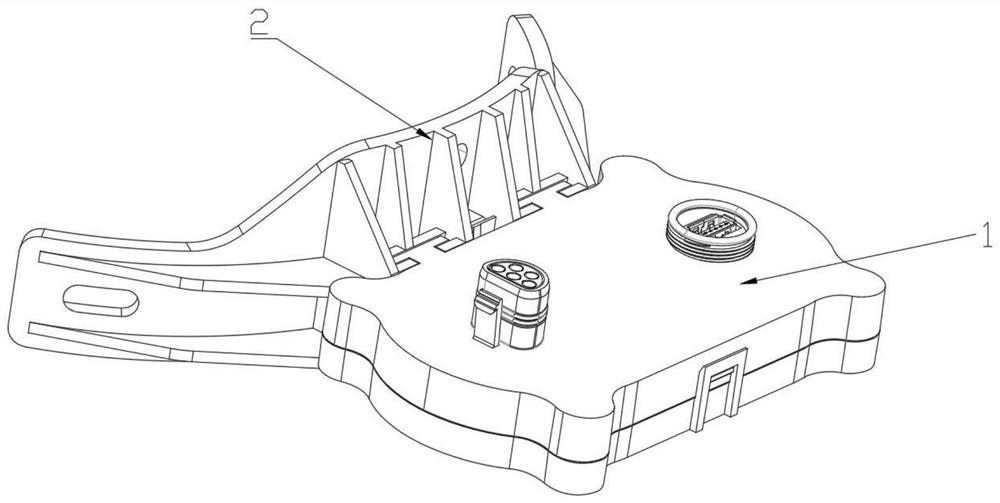
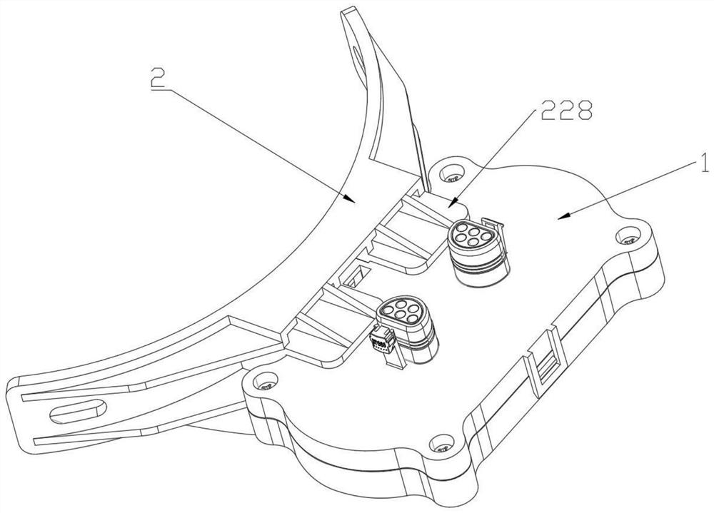
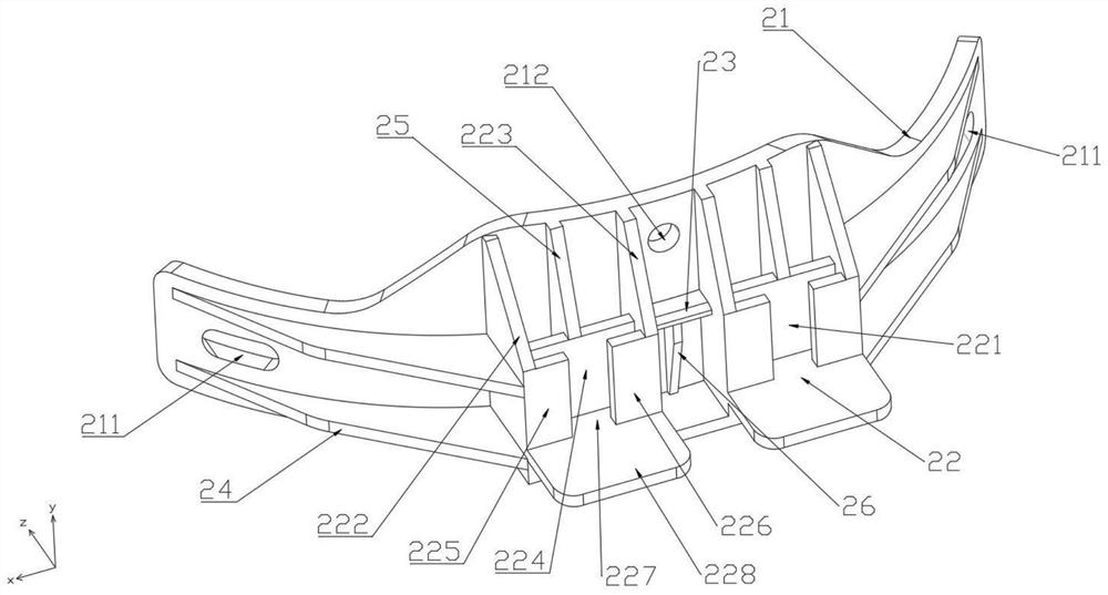
[0049] see Figure 1 to Figure 14 , figure 1 A schematic diagram of the three-dimensional structure of the dispenser provided by the embodiment of the present application at an angle; figure 2 A schematic diagram of the three-dimensional structure of the dispenser provided by the embodiment of the present application at another angle; image 3 A schematic diagram of the three-dimensional structure of the base at an angle provided for the embodiment of the present application; Figure 4 A schematic diagram of the three-dimensional structure of the base provided by the embodiment of the present application at another angle; Figure 5 An exploded schematic diagram of the housing provided for the embodiment of the present application at an angle; Figure 6 An exploded schematic diagram of the housing provided for the embodiment of the present application at another angle; Figure 7 A schematic diagram of the three-dimensional structure of the dispenser body provided by the em...


PUM


Abstract

The invention discloses a distributor. The distributor comprises a main body and a base, the main body is installed on the base, the main body comprises a housing, a circuit board and a plurality of pin assemblies, an accommodating cavity is formed in the housing, the circuit board is installed in the accommodating cavity, two sides of the housing are respectively provided with a plurality of connecting ports, the connecting ports are communicated with the containing cavity, the pin assembly comprises a contact pin seat and a plurality of pins installed in the pin seat, the pin assembly is installed in the connector, and the plurality of pins are respectively connected with the circuit board. According to the distributor, the assembling efficiency of the distributor is high, dismounting and mounting are convenient, the size is small, the connecting ports are formed in the two sides of the distributor, meanwhile, the pins are connected with the circuit board in an assembly mode, and the assembling speed and the assembling precision of the pins are greatly improved.

Description

technical field [0001] The invention relates to the technical field of connectors, in particular to a dispenser. Background technique [0002] A distributor is a device used for current distribution or signal distribution. It can divide one current or signal into multiple channels. Therefore, there will be multiple connection ports on the distributor, one for current or signal access, and the other It is used as an output port of current or signal to send current or signal to other equipment or other distributors. [0003] The existing distributors generally have connection ports set on the same side of the device, and the cables have a certain thickness, and in order to facilitate installation, the connection ports are usually arranged in a row. Therefore, the existing distribution The device is usually bulky and long, which is not conducive to portability and installation, and also increases the manufacturing cost. [0004] And in the process of use, some equipment is us...

Claims


Application Information

Patent Timeline
IPC IPC(8): H01R12/58H01R13/02H01R13/40H01R13/502H01R13/512H01R13/52H01R13/64H01R13/66H01R13/73
CPCH01R12/58H01R13/02H01R13/40H01R13/502H01R13/512H01R13/5213H01R13/64H01R13/665H01R13/73
Inventor 张威高昱
Owner 苏州丰年科技股份有限公司
Learn More