[0024] The technical solutions in the embodiments of the present invention will be clearly and completely described below with reference to the accompanying drawings in the embodiments of the present invention. Obviously, the described embodiments are only a part of the embodiments of the present invention, but not all of the embodiments. Based on the embodiments of the present invention, all other embodiments obtained by those of ordinary skill in the art without creative efforts shall fall within the protection scope of the present invention.
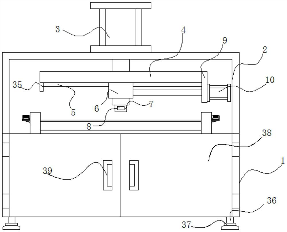
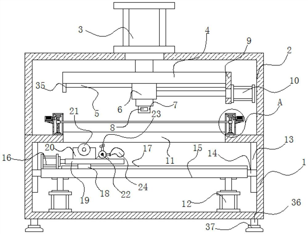
[0025] see Figure 1-6 , the present invention provides a technical solution: a double-channel glue coating head of a backplane folding glue coating machine, comprising a box body 1, the lower surface of the box body 1 is welded with four groups of support columns 36, and the lower surface of the four groups of support columns 36 is welded. Four sets of rubber bases 37 are fixedly installed by bolts, and the support columns 36 make the lower surface of the box 1 leave the ground, effectively preventing the stains on the ground from corroding the lower surface of the box 1, and the upper surface of the box 1 is welded with a U-shaped plate 2. The upper surface of the U-shaped plate 2 is fixedly installed with a first cylinder 3 by bolts, the end of the piston rod of the first cylinder 3 is fixedly installed with a first support plate 4 by bolts, and the lower surface of the first support plate 4 is provided with a first support plate 4. Slide rail 5, the first slide rail 5 is slidably connected with a first slider 6, the other end of the first slide rail 5 is welded with a limit plate 35, the limit plate 35 completely covers the end of the first slide rail 5, and the limit The plate 35 effectively prevents the first sliding block 6 from sliding out of the first sliding rail 5. The lower surface of the first sliding block 6 is fixedly installed with an automatic hot-melt glue machine 7 through bolts, and the automatic hot-melt glue machine 7 is fixedly installed with an automatic hot-melt glue machine 7. The double-channel glue applicator 8, the automatic hot-melt glue machine 7 and the double-channel glue applicator 8 are arranged perpendicular to each other, so that the PUR glue is applied between the backboards more evenly, and the double-channel glue applicator 8 is provided with fasteners The hole 803 and the PUR glue channel 805 are provided with a positioning pin 804 on the double-channel glue application head 8 , a wear-resistant sheet 806 is welded between the PUR glue channels 805 , and a fastener 802 is threadedly connected to the double-channel glue application head 8 , a vertical plate 9 is welded on the side of the first support plate 4, a second cylinder 10 is fixedly installed on the outer wall of the vertical plate 9 through bolts, and the end of the piston rod of the second cylinder 10 is fixedly installed on the first slider 6 through bolts. on the outer wall.
[0026] see figure 2 , the box body 1 is provided with a through hole 11, the upper surface of the inner cavity of the box body 1 is fixed with a third cylinder 12 by bolts, the inner wall of the box body 1 is provided with a second slide rail 13, and the second slide rail 13 is slidably connected There is a second slider 14, a second support plate 15 is welded between the second sliders 14, and the end of the piston rod of the third cylinder 12 is fixedly installed on the lower surface of the second support plate 15 by bolts. A fourth cylinder 16 is fixedly installed on the upper surface by bolts, and a third sliding rail 17 is arranged on the upper surface of the second supporting plate 15 , and a third sliding block 18 is slidably connected to the third sliding rail 17 . The third support plate 19 is installed on the surface by bolts, the end of the piston rod of the fourth cylinder 16 is installed on the outer surface of the third support plate 19 by bolts, and the upper surface of the third support plate 19 is installed with the first servo through bolts. The motor 20 and the dust suction fan 22, the air guide hood 23 sleeved on the suction pipe of the dust suction fan 22, the center of the air guide hood 23 and the center of the cutting knife 21 are on the same horizontal line in the transverse direction, and the The dust generated when cutting the back plate is quickly sucked into the dust bag 24 , the cutting blade 21 is fixedly installed on the output shaft of the first servo motor 20 , and the dust bag 24 is sleeved on the dust outlet pipe of the dust suction fan 22 . The box body 1 is fixedly installed with a double door 38 through hinges, and the outer surface of the double door 38 is fixedly installed with a door handle 39 through bolts.
[0027] see figure 2 and image 3, the upper surface of the box body 1 is fixedly installed with a cylindrical box 25 by bolts, and two sets of bearing seats 26 are fixed and installed on the inner wall of the cylindrical box 25 by bolts. A second bevel gear 31 is welded on it, a threaded sleeve 32 is threaded on the screw rod 27, a fourth support plate 28 is welded on the outer wall of the cylindrical box 25, and the upper surface of the fourth support plate 28 is fixed with bolts. Servo motor 29, oblique rods 34 are welded on the outer wall of the cylindrical box 25, the other end of the oblique rods 34 is welded on the lower surface of the fourth support plate 28, the outer wall of the cylindrical box 25, the inclined rods 34 and the fourth support plate 28 form a triangle structure, so that the second servo motor 29 is more firmly fixed on the upper surface of the fourth support plate 28, and the output shaft of the second servo motor 29 is keyed with the first bevel gear 30, the first bevel gear 30 and the first bevel gear 30. The two conical gears 31 are meshed and connected, a pressure plate 33 is welded between the threaded sleeves 32, and a through hole is formed on the cylindrical case 25.
[0028] Working principle: Put the four backboards together under the pressure plate 33, start the second servo motor 29, the rotation of the output shaft of the second servo motor 29 drives the pressure plate 33 to compress the edge of the back plate downward, and start the third servo motor 29. The air cylinder 12, the fourth air cylinder 16, the first servo motor 20 and the dust suction fan 22, the piston rod of the third air cylinder 12 drives the cutting knife 21 to rise or fall, and the piston rod of the fourth air cylinder 16 drives the cutting knife 21 to the left or right Move, the rotation of the output shaft of the first servo motor 20 drives the cutting knife 21 to rotate at a high speed to cut the back plate. After the edges are cut and milled, the PUR glue is injected into the automatic hot-melt glue machine 7, and the first air cylinder 3 is activated. , the second air cylinder 10 and the automatic hot melt glue machine 7, the piston rod of the first air cylinder 3 drives the double-channel glue applicator head 8 to rise or fall, and the piston rod of the second air cylinder 10 drives the double-channel glue applicator head 8 to the left or right Move, the automatic hot-melt glue machine 7 hot-melts the PUR glue, and the dual-channel glue applicator 8 evenly coats the hot-melt PUR glue between the two backboards, leaving 0.1-1mm above and below the outer surface of the two substrates , Take out the backplane after cooling for 10-20 seconds. Since the PUR glue has a strong willfulness, the adhesive layer will bond the two substrates together, so that the two backplanes can be unfolded 180 degrees. The device can be used in one station. Processing four pieces of products ensures the quality and doubles the efficiency, thus reducing the production of finished products; products that used to require two pieces of equipment a day can now be finished with one piece of equipment in one day, reducing equipment investment, thus It also reduces energy consumption, is more environmentally friendly and more economical; saves labor, and the work that two people do in a day can now be done by one person in a day.
[0029] Finally, it should be noted that the above are only preferred embodiments of the present invention, and are not intended to limit the present invention. Although the present invention has been described in detail with reference to the foregoing embodiments, for those skilled in the art, it is still possible to Modifications are made to the technical solutions described in the foregoing embodiments, or equivalent replacements are made to some of the technical features. Any modifications, equivalent replacements, improvements, etc. made within the spirit and principles of the present invention shall be included in the present invention. within the scope of protection.