Energy dissipation supporting structure, energy dissipation supporting frame system and construction method of energy dissipation supporting frame system

An energy-dissipating support and frame system technology, applied in building components, building structures, and earthquake resistance, can solve the problems of building structure damage, earthquake energy dissipation, and poor earthquake resistance, so as to absorb vibration energy, improve structural rigidity, The effect of simple assembly

Active Publication Date: 2021-07-16
HEBEI UNIV OF TECH
View PDF7 Cites 0 Cited by
  • Summary
  • Abstract
  • Description
  • Claims
  • Application Information

AI Technical Summary

Problems solved by technology

[0004]The traditional anti-seismic method is to dissipate the seismic energy through the plastic deformation of the structure itself, which is easy to cause damage or even collapse of the building structure, and the anti-seismic effect is poor

Method used


Image

  • Energy dissipation supporting structure, energy dissipation supporting frame system and construction method of energy dissipation supporting frame system
  • Energy dissipation supporting structure, energy dissipation supporting frame system and construction method of energy dissipation supporting frame system
  • Energy dissipation supporting structure, energy dissipation supporting frame system and construction method of energy dissipation supporting frame system

Examples


Embodiment 1

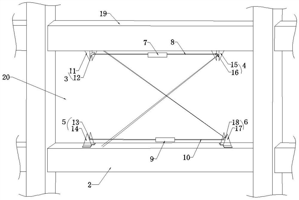
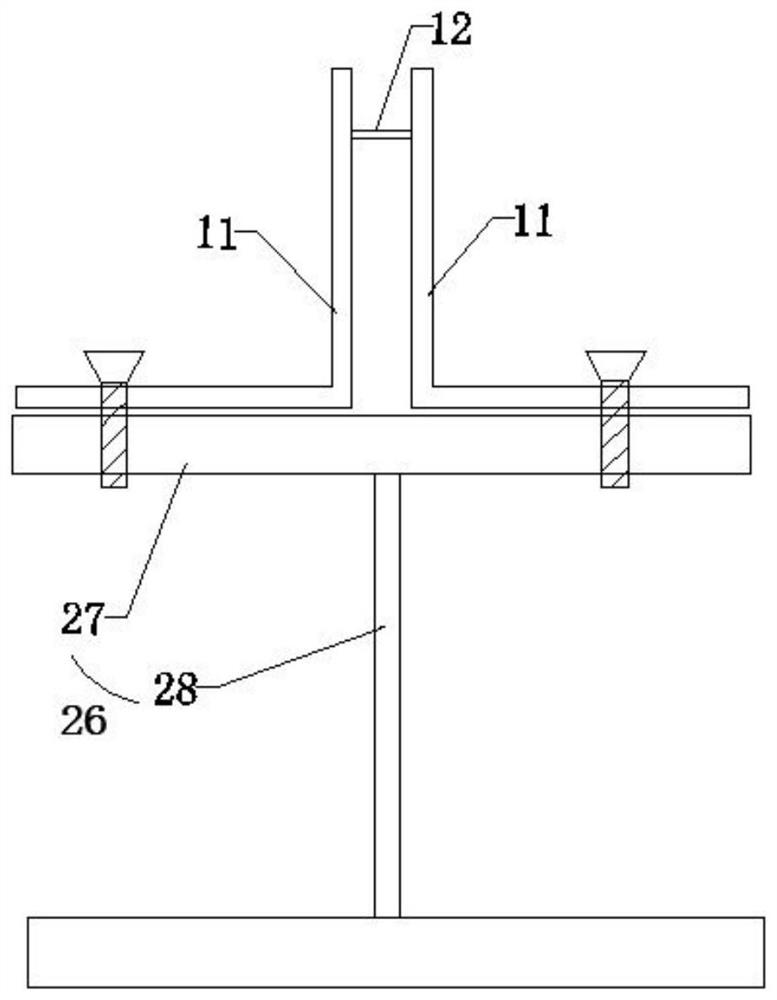
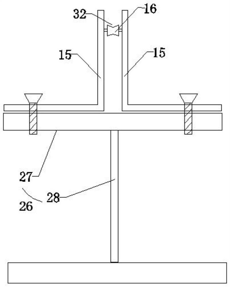
[0046] Please refer to figure 1 An energy-dissipating support structure provided for this application is installed in a frame unit 20. The frame unit 20 includes two prefabricated beams, namely an upper prefabricated beam 1 located relatively above and a lower prefabricated beam 2 located relatively below. The energy-dissipating support structure includes a support assembly; the support assembly includes: a first fixing member 3 installed at the bottom of the upper precast beam 1, a first steering member 4, and a second fixing member installed at the top of the lower precast beam 2 The fixing part 5, the second steering part 6;

[0047] A first energy dissipation device 7 is provided between the first fixing member 3 and the first steering member 4, and a first steel strand 8 is connected to both ends of the first energy dissipation device 7, and the first steel strand One free end of the wire 8 is connected to the first fixing member 3, and the other free end of the first st...

Embodiment 2

[0069] Such as Figure 4 Shown is an energy-dissipating support frame system provided by this embodiment, including the energy-dissipating support structure described above, and a support frame 19 formed by a plurality of prefabricated columns and a plurality of prefabricated beams; the support frame 19 has a plurality of frame units 20, and the energy dissipation support structure is installed in the frame units 20;

[0070] The prefabricated column includes a square steel pipe 21 and a diaphragm 22 installed in the square steel pipe 21, a column longitudinal reinforcement 23; the diaphragm 22 is provided with a pouring hole 24 and is used to install the column longitudinal reinforcement 23 The mounting hole 25;

[0071] The prefabricated beam includes an I-beam 26 and beam longitudinal bars 31 welded on the I-beam 26; the I-beam 26 is exposed at both ends of the prefabricated beam;

[0072] The flange 27 of the I-beam 26 is welded to the side wall of the square steel pipe ...

Embodiment 3

[0082] Such as Figure 7 Shown is the construction method of the energy-dissipating support frame system described in the above structure provided by this embodiment, including the following steps:

[0083] Step S1: the factory manufactures the prefabricated columns and beams;

[0084] When making the prefabricated column, the installation hole 25 and the pouring hole 24 are drilled on the diaphragm 22; the diaphragm 22 is arranged in the square steel pipe 21; 23 passing through the installation hole 25, and binding with stirrups; pouring is performed after the binding is completed, so that the concrete passes through the pouring hole 24 and is compacted in the column, and the prefabricated column is obtained after curing;

[0085] When making the prefabricated beam, the beam longitudinal reinforcement 31 is welded on the I-beam 26 and bound with stirrups; The bolt holes 30 are opened on the web 28; concrete is poured and cured to obtain a prefabricated beam.

[0086] Step S2...


PUM


Abstract

The invention provides an energy dissipation supporting structure, an energy dissipation supporting frame system and a construction method of the energy dissipation supporting frame system. The energy dissipation supporting structure comprises a supporting assembly, wherein the supporting assembly comprises a first fixing piece and a first steering piece which are mounted at the bottom of a upper prefabricated beam, and a second fixing piece and a second steering piece which are mounted at the top of a lower prefabricated beam; a first energy dissipation device is arranged between the first fixing piece and the first steering piece, the two ends of the first energy dissipation device are connected with first steel strands, one free end of each first steel strand is connected with the first fixing piece, and the other free end of each first steel strand bypasses the first steering piece to be connected with the lower prefabricated beam; a second energy dissipation device is arranged between the second fixing piece and the second steering piece, the two ends of the second energy dissipation device are connected with second steel strands, one free end of each second steel strand is connected with the second fixing piece, and the other free end of each second steel strand bypasses the second steering piece to be connected with the upper prefabricated beam. The energy dissipation supporting structure is easy to assemble, has a good anti-seismic effect and is beneficial to improving the building strength.

Description

technical field [0001] The present disclosure generally relates to the construction field, and specifically relates to an energy-dissipating support structure, an energy-dissipating support frame system and a construction method thereof. Background technique [0002] As the volume of construction increases exponentially, prefabricated buildings have become an increasingly common construction method. The prefabricated construction method prefabricates components in the factory, and assembles, connects, pours the components at the construction site, and finally forms the final building. [0003] The massive destruction and collapse of buildings in earthquakes is the direct cause of earthquake disasters. Therefore, how to achieve a more stable connection and how to better resist natural disasters such as earthquakes are important indicators related to the safety performance of buildings. [0004] The traditional anti-seismic method is to dissipate the seismic energy through t...

Claims


Application Information

Patent Timeline
Patent Type & Authority Applications(China)
IPC IPC(8): E04B1/20E04B1/21E04B1/98E04H9/02
CPCE04B1/20E04B1/21E04B1/98E04H9/021E04H9/025E04B1/2403E04B1/215
Inventor 张健新戎贤张标王理达李艳艳刘平张晓巍
Owner HEBEI UNIV OF TECH
Why Eureka
Try Eureka