Axial classification combustor
A staged combustion and secondary combustion technology, which is applied in combustion chambers, combustion methods, combustion equipment, etc., can solve the problems of inability to meet NOx emission standards and increase emissions, and achieve shortened residence time, low NOx emissions, and improved air uniformity Effect
- Summary
- Abstract
- Description
- Claims
- Application Information
AI Technical Summary
Problems solved by technology
Method used
Image
Examples
Embodiment 1
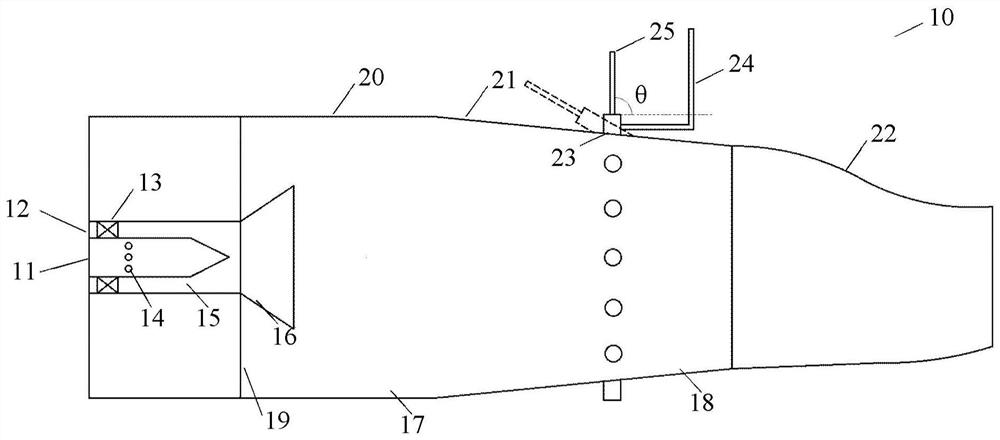
[0040] figure 1 A structural view of the axially staged combustor provided by the embodiment of the present invention is schematically shown. Such as figure 1 As shown, the axially staged combustor 10 may include:
[0041] The combustion chamber includes a main combustion zone 17 and a secondary combustion zone 18. The main combustion zone 17 is arranged in the upstream section of the combustion chamber, surrounded by its front wall 19 and a primary cylindrical wall 20 . The secondary combustion zone 18 is arranged in the downstream section of the combustion chamber, adjacent to the main combustion zone 17 in the axial direction, and surrounded by the secondary cylindrical wall surface 21 . The rear end of the secondary combustion zone 18 communicates with a transition section 22 .
[0042] In a feasible mode of this embodiment, the primary equivalent ratio of the main combustion zone 17 can adopt, for example, a lean premixed combustion mode, and the high-temperature flue...
Embodiment 2
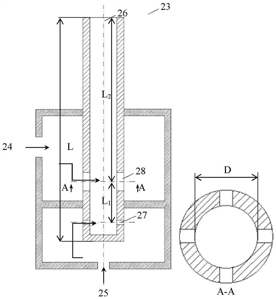
[0053] The secondary nozzle of the axially staged combustor provided in this implementation adopts a micro-mixing nozzle structure. figure 2 A schematic diagram of the structure of the secondary nozzle provided by this embodiment is shown. Such as figure 2 As shown, the secondary nozzle 23 is provided with a nozzle structure outlet 26 towards the secondary combustion zone 18, and the cross section of the nozzle structure outlet 26 is circular (such as figure 2 Shown in A-A), its diameter D is the amount in millimeters. In a feasible manner of this embodiment, the specific range may be, for example, 1mm≤D≤20mm, preferably 5mm≤D≤20mm, which is not limited in the present invention.
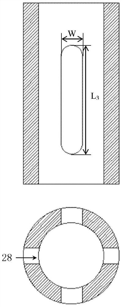
[0054] Secondary nozzle 23 is provided with nozzle fuel inlet 27 and nozzle air inlet 28, and the cross-section of nozzle fuel inlet 27 structure is as follows image 3 As shown, the cross-section of the nozzle fuel inlet 27 structure is as Figure 4 As shown, the nozzle fuel inlet 27 and the ...
Embodiment 3
[0062] In this implementation, an axially staged burner with specific numerical operating parameters and structural parameters is selected for combustion tests.
[0063] Specifically, in a feasible mode of this embodiment, the total equivalent ratio is 0.727, the primary air flow rate is 900SLM, the primary fuel flow rate is 66.2SLM, the secondary load ratio FS is 30%, and the secondary equivalent ratio Φ 2 Take 0.8, the equivalent ratio of the main combustion zone Φ 1 Take 0.7. The secondary nozzle 23 is arranged vertically to the centerline of the classification system, θ is 90°, the diameter D of the secondary nozzle 23 is 5 mm, and the number of secondary nozzles 23 is 8. At this time, the jet flux ratio J is about 20. The overall length L of the secondary nozzle 23 is 7D, and the length L between the nozzle fuel inlet 27 and the nozzle air inlet 28 1 Take 2D, the length L between the nozzle air inlet 28 and the secondary nozzle outlet 26 section 2 Take 5D. Number N of...
PUM
 Abstract
Description
Claims
Application Information
 - R&D
- Intellectual Property
- Life Sciences
- Materials
- Tech Scout
- Unparalleled Data Quality
- Higher Quality Content
- 60% Fewer Hallucinations
Browse by: Latest US Patents, China's latest patents, Technical Efficacy Thesaurus, Application Domain, Technology Topic, Popular Technical Reports.
© 2025 PatSnap. All rights reserved.Legal|Privacy policy|Modern Slavery Act Transparency Statement|Sitemap|About US| Contact US: help@patsnap.com


