
Fault positioning optical/electric monitoring cable

A fault location and electrical monitoring technology, applied in fault location, high resistance measurement, fault detection according to conductor type, etc., can solve the problems of prolonging the obstacle duration, difficult to locate the fault point, affecting the smooth communication, etc., to reduce financial resources and cost. The waste of manpower, shortening the repair time, and improving the efficiency of the repair

Pending Publication Date: 2021-07-16
李佑进
View PDF0 Cites 0 Cited by
  • Summary
  • Abstract
  • Description
  • Claims
  • Application Information

AI Technical Summary

Problems solved by technology

If the maintenance team does not have a detailed "ground length-road length-cable length" comparison table, once the optical cable line fails, if there is no fault clue on the site surface, it is often difficult for the emergency repair personnel to accurately locate the fault based on the terminal test data and drawings given by the computer room It is very likely that there is a large error with the actual fault point, and it is necessary to find the nearby joint point, excavate the joint box, re-test the positioning and recovery; excavating and opening the joint box is also easy to damage the joint box, resulting in original faults during the splicing process. The loss of connectors increases, and in serious cases, the business is interrupted, and the connection needs to be re-opened, which greatly prolongs the duration of the failure, affects the efficiency of emergency repairs, and even seriously affects the smooth communication

Method used


Image

  • Fault positioning optical/electric monitoring cable
  • Fault positioning optical/electric monitoring cable
  • Fault positioning optical/electric monitoring cable

Examples


Embodiment Construction

[0029] In order to make the object, technical solution and advantages of the present invention clearer, the present invention will be further described in detail below in conjunction with the accompanying drawings and embodiments. It should be understood that the specific embodiments described here are only used to explain the present invention, not to limit the present invention.

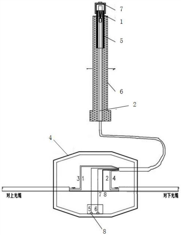
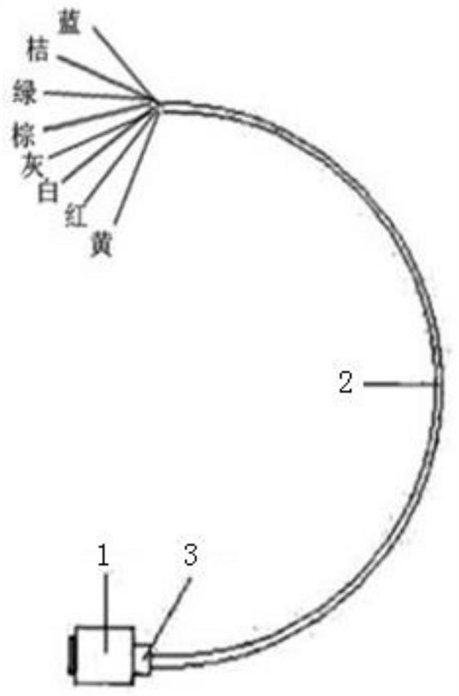
[0030] A fault location optical / electrical monitoring cable, such as figure 2 and Figure 4 shown; includes:

[0031] The monitoring cable includes a female insulating sealing head 1, and light / cable 2, sealing elements 3, such as figure 2 shown;

[0032] The test cable comprises a male insulating sealing head 16, light / cable 17 and test clips (blue, orange, green, brown, grey, white, red, yellow) for testing, such as Figure 4 shown;

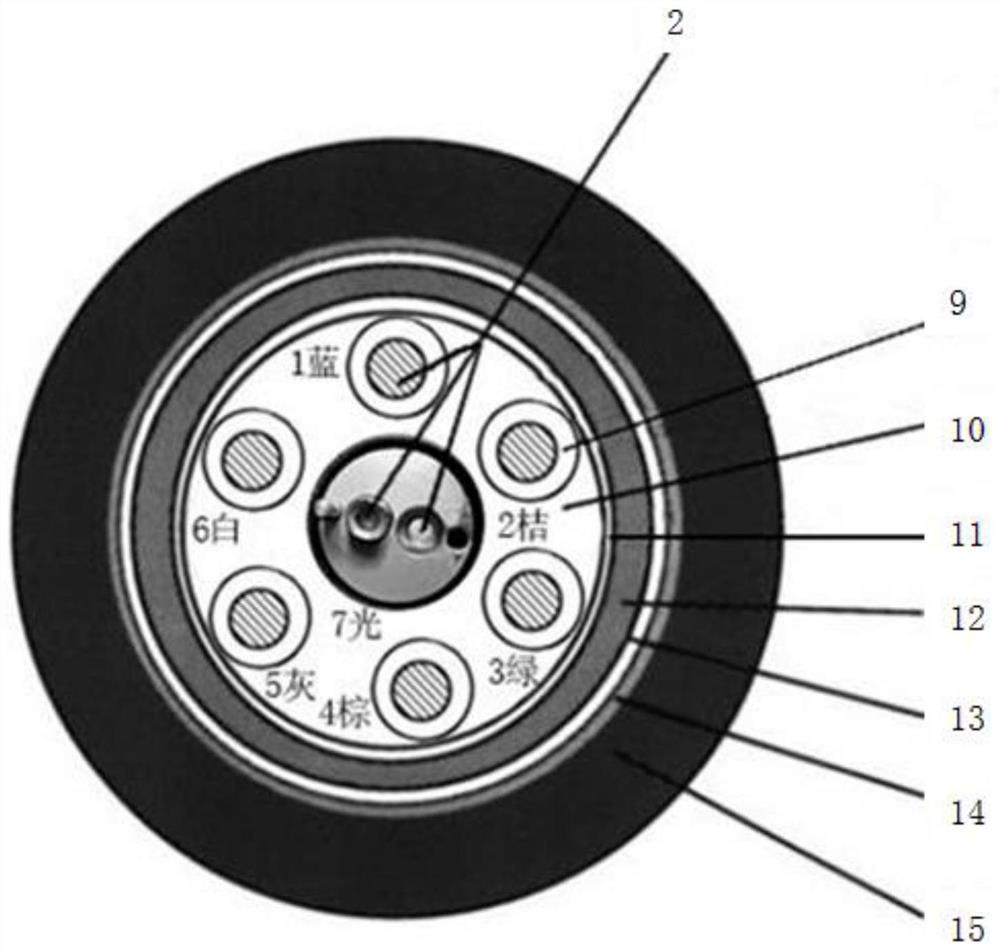
[0033] The optical / cable 2 includes 6 stranded cables, 2 optical cables and filled solid wires, one end of which passes through the monitoring marker 6 and i...


PUM


Abstract

The invention provides a fault positioning optical / electric monitoring cable. The fault positioning optical / electric monitoring cable comprises a female insulation sealing head, an optical / electric cable and a monitoring markstone pre-embedded near an optical cable connector box, a steel pipe matched with the monitoring markstone is embedded in the top of the monitoring markstone, and the lower end of the female insulation sealing head is clamped to the top of the steel pipe matched with the monitoring markstone through a sealing element; one end of the optical / electric cable is connected with the female insulation sealing head, and the other end of the optical / electric cable penetrates through the monitoring markstone matching steel pipe and the monitoring markstone in sequence and is connected to the upper optical cable and the lower optical cable of the optical cable connector box; The fault positioning optical / electric monitoring cable also comprises a male insulation sealing head, and the male insulation sealing head is matched with the female insulation sealing head; and the male insulation sealing head is connected with a test light / cable connected with a tester. The device can accurately position a fault point through the fault positioning optical / electric monitoring cable without digging and opening the connector box, and is simple and convenient to operate, safe and reliable.

Description

technical field [0001] The invention belongs to the technical field of direct-buried optical cable troubleshooting, and in particular relates to a fault location optical / electrical monitoring cable. Background technique [0002] Long-distance direct-buried optical cable lines have long communication distances. During the construction, emergency repair, and drawing of optical cable lines, there are cases where the length of optical cables reserved for crossing roads, rivers, bridges, and joints does not meet the specifications. If the maintenance team does not have a detailed "ground length-road length-cable length" comparison table, once the optical cable line fails, if there is no fault clue on the site surface, it is often difficult for the emergency repair personnel to accurately locate the fault based on the terminal test data and drawings given by the computer room It is very likely that there is a large error with the actual fault point, and it is necessary to find the...

Claims


Application Information

Patent Timeline
Patent Type & Authority Applications(China)
IPC IPC(8): G01M11/02G01M3/04G01R31/08G01R31/12G01R27/02
CPCG01M3/04G01M11/02G01R27/025G01R31/083G01R31/1272
Inventor 李佑进
Owner 李佑进
Learn More