
General radar antenna amplitude jitter elimination method

A radar antenna and antenna technology, which is applied in the field of general radar underground target detection, can solve the problems of decreasing target recognition rate, affecting the accuracy of data processing results, affecting target recognition, etc., and achieving the effect of facilitating data processing.

Inactive Publication Date: 2021-07-16
中国电波传播研究所
View PDF8 Cites 0 Cited by
  • Summary
  • Abstract
  • Description
  • Claims
  • Application Information

AI Technical Summary

Problems solved by technology

The magnitude of the antenna amplitude represents the strength of the signal energy. In the raw data acquired by the radar, the antenna amplitude jitter will affect the stability of the data
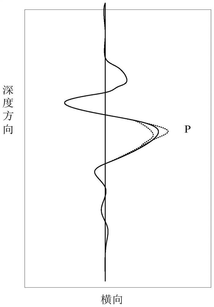
In the case of large antenna amplitude jitter, the peak point of the pulse signal broadens from a dot to a line horizontally, and the radar data of the radar single-channel waveform jitters left and right along the abscissa, which will affect the accuracy of the later data processing results
In addition, antenna amplitude jitter will not only affect the target imaging quality, but also affect target recognition. If the antenna amplitude jitter is large, the imaging quality will decrease and the target recognition rate will also decrease.

Method used


Image

  • General radar antenna amplitude jitter elimination method
  • General radar antenna amplitude jitter elimination method
  • General radar antenna amplitude jitter elimination method

Examples


Embodiment 1

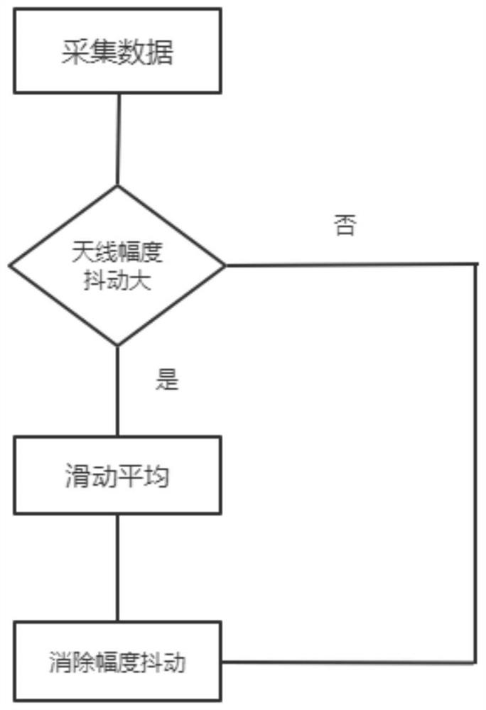
[0033] Embodiment 1, this embodiment discloses a general radar antenna amplitude jitter elimination method, such as figure 2 As shown, the moving average algorithm can eliminate the antenna amplitude jitter. When using the moving average, it is necessary to set the size of the sliding window, calculate the average value of the data in the window, and replace the profile data with the radar profile data minus the average value. The specific steps are as follows:

[0034] Step 1. Obtain radar data, connect the antenna and the radar host with a cable, place the antenna on a foam body whose height is twice the wavelength of the antenna's center frequency, and place the foam body on a copper-clad board that is four times the wavelength of the antenna's center frequency. The copper-clad board and The central axis of the antenna coincides, and the collected data is saved, and the number of data channels is greater than 1000;

[0035] Step 2, read the sampling point, time window, fre...

Embodiment 2

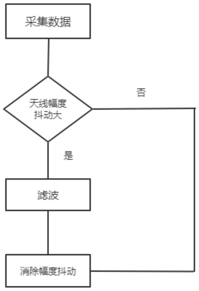
[0043] Embodiment 2, this embodiment discloses a general radar antenna amplitude jitter elimination method, such as image 3 shown, including the following steps:

[0044] Step 1. Obtain radar data, connect the antenna and the radar host with a cable, place the antenna on a foam body whose height is twice the wavelength of the antenna's center frequency, and place the foam body on a copper-clad board that is four times the wavelength of the antenna's center frequency. The copper-clad board and The central axis of the antenna coincides, and the collected data is saved, and the number of data channels is greater than 1000;

[0045] Step 2, read the sampling point, time window, frequency, channel number and other parameters of each original data, and shave the first 200 channel data and the last 200 channel data of the original data;

[0046] Step 3, use the filtering method to eliminate the amplitude jitter of the general radar antenna:

[0047] A bandpass filter is designed f...


PUM


Abstract

The invention discloses a general radar antenna amplitude jitter elimination method comprising the following steps: step 1, acquiring radar data, and connecting an antenna and a radar host by using a cable; step 2, reading parameters of each piece of original data; and step 3, eliminating the amplitude jitter of the general radar antenna by adopting a moving average or filtering method. According to the method disclosed by the invention, the radar data is processed by using the moving average or filtering method, and the influence caused by excessive amplitude jitter of the antenna is counteracted, so that the original data is better presented, and data processing and imaging, identification and research of an underground target are facilitated.

Description

technical field [0001] The invention belongs to the field of general radar underground target detection, in particular to a general radar antenna amplitude shake elimination method in the field. Background technique [0002] Ground-penetrating radar technology utilizes the penetration ability of specific frequency electromagnetic waves to the surface and underground media, emits electromagnetic waves, and then obtains the echo signal of the underground target, and obtains the imaging of the underground target by processing the echo signal, thereby positioning the underground target. identification and research. The magnitude of the antenna amplitude represents the strength of the signal energy. In the raw data acquired by the radar, the antenna amplitude jitter will affect the stability of the data. In the case of large antenna amplitude jitter, the peak point of the pulse signal broadens from a dot to a line horizontally, and the radar data of the radar single-channel wave...

Claims


Application Information

Patent Timeline
Patent Type & Authority Applications(China)
IPC IPC(8): G01S13/88G01S7/02
CPCG01S13/885G01S7/02
Inventor 程星王君超王成浩
Owner 中国电波传播研究所
Learn More