Optical fiber cutter sliding block using elastic blade support
A cleaver and blade technology, applied in the direction of coupling of optical waveguides, etc., can solve the problems of uneven quality of optical fiber scratches, uneven force on the blade edge, shortening the service life of the blade, etc., so as to improve the scratch accuracy and reduce the Clamping force requirements, the effect of prolonging the service life
- Summary
- Abstract
- Description
- Claims
- Application Information
AI Technical Summary
Problems solved by technology
Method used
Image
Examples
Embodiment Construction
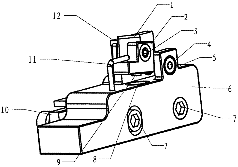
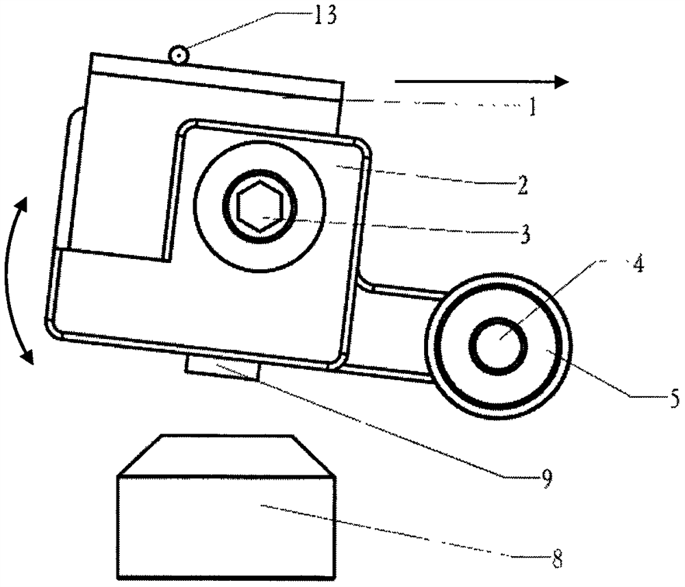
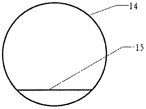
[0040] figure 1It is the front view of the optical fiber cleaver slider using the elastic blade bracket; 1. The blade is installed in the groove of the 2. Elastic blade bracket, and is locked from the side by the 3. Blade fixing screw; when one cutting edge is worn, 4. The blade can be taken out and installed on 2. the elastic blade holder after rotating 180 degrees; The other is blocked and cannot be seen), and is fixed on the 6. slider by the bearing, corresponding to the opening position. At this time, 2. The elastic blade bracket can move in an arc with the 5. Blade bracket bearing as the center. The movement is limited by the 11. blade bracket limiter to ensure that it will not interfere with other structural operations on the fiber optic cleaver. 7. The slider fixing screw passes through the two corresponding holes on the 6. slider. (One of them is a waist-shaped hole, so that 6. Slider, the vertical position can be fine-tuned) Fix the whole assembly on one side of 10. ...
PUM
 Abstract
Description
Claims
Application Information
 - R&D
- Intellectual Property
- Life Sciences
- Materials
- Tech Scout
- Unparalleled Data Quality
- Higher Quality Content
- 60% Fewer Hallucinations
Browse by: Latest US Patents, China's latest patents, Technical Efficacy Thesaurus, Application Domain, Technology Topic, Popular Technical Reports.
© 2025 PatSnap. All rights reserved.Legal|Privacy policy|Modern Slavery Act Transparency Statement|Sitemap|About US| Contact US: help@patsnap.com


