Two-component dispensing valve, glue injection machine with same and use method of glue injection machine

A dispensing valve, two-component technology, applied in the field of dispensing valve, can solve the problems of increasing cleaning frequency, complex internal structure, affecting practicability, etc., and achieve the effect of improving use efficiency, improving production efficiency, and reducing damage

Pending Publication Date: 2021-07-20
烟台拓展聚氨酯设备有限公司
View PDF10 Cites 4 Cited by
  • Summary
  • Abstract
  • Description
  • Claims
  • Application Information

AI Technical Summary

Problems solved by technology

[0007] Therefore, the cleaning process of the existing plunger dispensing valve is complex and cumbersome, and the internal structure is complicated, and it is extremely inconvenient to disassemble and install, which greatly affects the practicability; its own suction function increases the cleaning frequency and affects the normal operation. usage time
[0008] Patent CN207287934U is a cleaning device for a two-component dispensing valve, which discloses using a needle valve and a cleaning agent to clean the A glue channel or the B glue channel, and can also clean both the A glue channel and the B glue channel. The mixing tube is cleaned, but an additional needle valve is required, which increases the cost of use and maintenance

Method used


Image

  • Two-component dispensing valve, glue injection machine with same and use method of glue injection machine
  • Two-component dispensing valve, glue injection machine with same and use method of glue injection machine
  • Two-component dispensing valve, glue injection machine with same and use method of glue injection machine

Examples


Embodiment

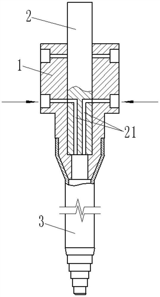
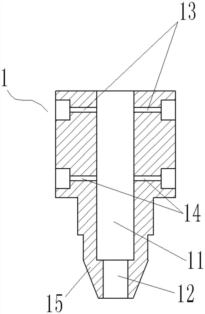
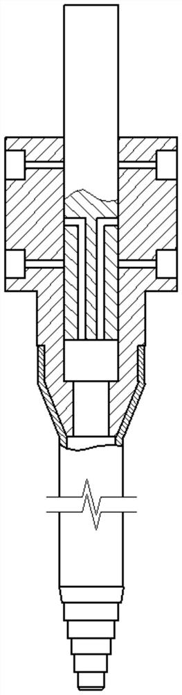
[0032] see Figure 1 ~ Figure 4 , the present invention provides a two-component dispensing valve, comprising: a valve body 1 and a valve stem 2; the lower end of the valve body 1 is provided with an integrated joint 15, and the joint 15 is used to seal the static mixing pipe 3; the valve body 1 is provided with a vertical and through sliding chamber 11; the side of the valve body 1 is provided with an air inlet 13 and a feeding hole 14 communicating with the sliding chamber 11 in sequence from top to bottom, the air inlet 13 and the feeding hole The number of 14 is 2 respectively; wherein, the air inlet 13 is used for inputting water and / or air;

[0033] The valve stem 2 here slides in a sealed manner in the sliding chamber 11. The bottom of the valve stem 2 is provided with a glue channel 21. One end of the glue channel 21 can match and communicate with the air inlet 13 and the feed hole 14, and the other end It is used to output glue; the number of glue channels 21 is 2; t...


PUM


Abstract

The invention relates to the technical field of dispensing valves, in particular to a two-component dispensing valve. The two-component dispensing valve comprises a valve body and a valve rod; an integrated connector is arranged at the lower end of the valve body and used for being connected with a static mixing pipe in a sealed manner; a vertical and through sliding cavity is formed in the valve body; the side face of the valve body is sequentially provided with air intake holes and feeding holes from top to bottom, the air intake holes and the feeding holes are communicated with the sliding cavity, the number of the air intake holes is two, and the number of the feeding holes is two; the valve rod slides in the sliding cavity in a sealed manner, glue solution channels are formed in the bottom of the valve rod, one ends of the glue solution channels can be matched with and communicated with the air intake holes and the feeding holes, and the other ends of the glue solution channels are used for outputting glue solution; the number of the glue solution channels is two; and the feeding holes are always in complete contact with the valve rod. The invention further provides a glue injection machine with the two-component dispensing valve and a using method of the glue injection machine, the glue injection, glue stopping and cleaning processes of the dispensing valve are achieved through the arrangement of the positions of the glue solution channels, the air intake holes and the feeding holes, the dispensing valve is simple in structure and convenient to use, and the cost is reduced.

Description

technical field [0001] The invention relates to the technical field of dispensing valves, in particular to a two-component dispensing valve, a glue injection machine with the same, and a method for using the glue injection machine. Background technique [0002] The dispensing valve is a kind of glue dispensing device, which is commonly used in the dispensing of AB glue, double-liquid epoxy resin glue, double-liquid crystal glue, acrylic blue-red glue, double-liquid silica gel, etc. It is widely used in optoelectronics, biochemistry, semiconductors and automobiles. And other industries, according to the drive mode is usually divided into two kinds of pneumatic and electric. [0003] Pneumatic dispensing valves usually include: a cylinder assembly, a valve body assembly, and a silo connected sequentially from top to bottom. The cylinder assembly is connected with a solenoid valve, which drives the cylinder assembly to move up and down to open and close the glue; according to ...

Claims


Application Information

Patent Timeline
Patent Type & Authority Applications(China)
IPC IPC(8): B05C5/02B05B15/55
CPCB05C5/02B05B15/55
Inventor 鹿敏
Owner 烟台拓展聚氨酯设备有限公司
Why Eureka
Try Eureka