Supporting device for portable electronic equipment and wireless charging supporting device
A technology for supporting devices and electronic equipment, applied in the direction of circuit devices, battery circuit devices, mechanical equipment, etc., can solve the problems that the viewing angle cannot be adjusted at will, increased or reduced, stiff and cannot be folded, etc.
- Summary
- Abstract
- Description
- Claims
- Application Information
AI Technical Summary
Problems solved by technology
Method used
Image
Examples
Embodiment 1
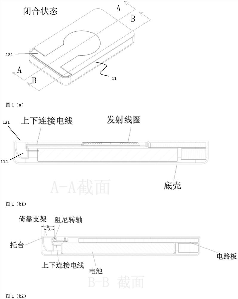
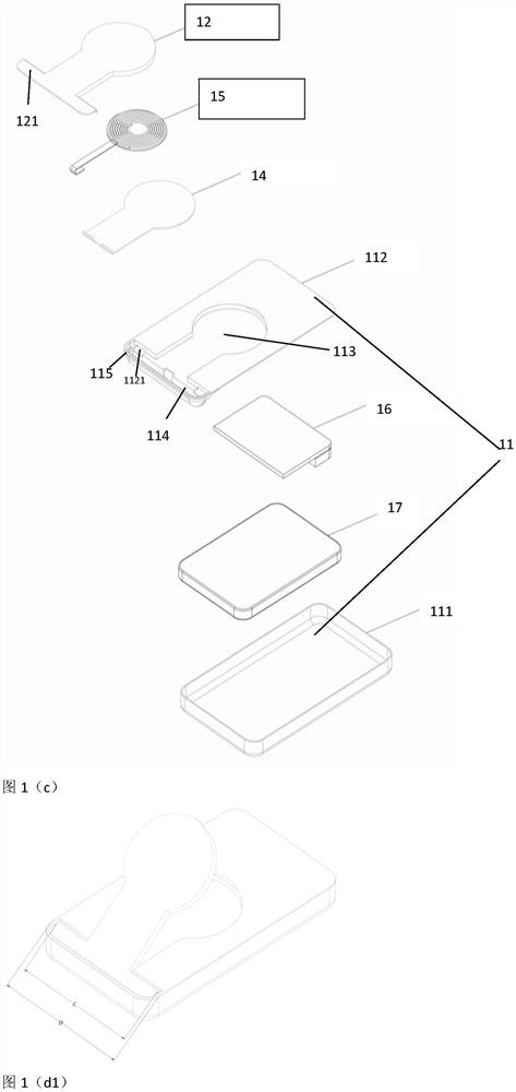
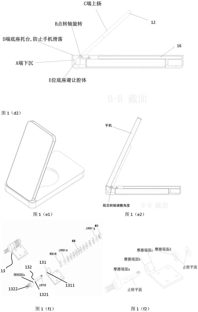
[0026] In the first aspect, Embodiment 1 of the present application provides a supporting device for portable electronic equipment, including a supporting body 11 and a bracket 12, the bracket is a flat structure, the supporting body 11 is a supporting base, and the supporting body 11 is a supporting base. The main body (or support base) 11 is composed of a bottom shell 111 and a pallet shell 112 , the pallet shell 112 is fixedly mounted on the bottom shell 111 , and the pallet shell 112 is provided with a bracket groove 113 for accommodating the bracket 12 . The front end of the bracket 12 has an integrally formed convex portion 121 (that is, the edge of the bracket extends outwards with a flange, and the flange and the bracket main body are on the same plane), and the pallet shell 112 opposite to the convex portion 121 has a An integrally formed groove 114, the width of the convex part is smaller than the width of the pallet shell, the space size of the groove 114 is at least...
Embodiment 2
[0038] Embodiment 2 of the present application is an improvement made on the basis of the supporting device in Embodiment 1. The structure of the supporting device in Embodiment 2 is substantially the same as that in Embodiment 1, except that: the supporting body (supporting base) 21 The upper surface of the upper surface is not provided with a support groove, and the support 22 can be horizontally placed on the upper surface of the support main body after being connected with the support main body through a damping shaft mechanism. The width C of the bracket at the front end of the damping shaft mechanism is smaller than the width D of the supporting body, and the width at the rear end of the damping shaft mechanism is basically the same as the width of the supporting body, which is beneficial to the beautiful appearance. In addition, in the embodiment of the present application, the support device is configured with a thick type, that is, the support body is designed with a t...
Embodiment 3
[0043] Embodiment 3 of the present application provides another support device with a structure different from that of Embodiments 1 and 2. The specific description is as follows:
[0044] The supporting device includes a supporting main body mechanism and a rotating connection mechanism, the supporting main body mechanism is a base 31, the base 31 has an integrally formed retaining bar 314 along the circumferential direction of its edge, and the rotating connecting mechanism is a flat plate-shaped lean-to Plate 32, the base 31 and the backing plate 32 are connected by a damping shaft mechanism 33 near the front end, and a base opening 311 is opened on the base 31 at the connection position between the backing plate and the base, and the base opening is used to accommodate the backing plate The front part of the front end rotates around the base in the range of 0-90°. When the leaning plate 32 rotates in the range of 0-90° through the damping shaft mechanism 33, the damping sh...
PUM
 Abstract
Description
Claims
Application Information
 - R&D
- Intellectual Property
- Life Sciences
- Materials
- Tech Scout
- Unparalleled Data Quality
- Higher Quality Content
- 60% Fewer Hallucinations
Browse by: Latest US Patents, China's latest patents, Technical Efficacy Thesaurus, Application Domain, Technology Topic, Popular Technical Reports.
© 2025 PatSnap. All rights reserved.Legal|Privacy policy|Modern Slavery Act Transparency Statement|Sitemap|About US| Contact US: help@patsnap.com


