
Antenna, antenna module and wireless network equipment

An antenna module and antenna technology, applied in the field of communication, can solve the problems of deteriorating WiFi performance and increasing the size of wireless devices.

Active Publication Date: 2021-07-20
HUAWEI TECH CO LTD
View PDF11 Cites 2 Cited by
  • Summary
  • Abstract
  • Description
  • Claims
  • Application Information

AI Technical Summary

Problems solved by technology

[0002] The specifications of home network wireless communication products are developing very fast from 2*2, 4*4 to 8*8, and the frequency bands are also developing from 2G, 5G to 6G, and even continue to expand in the millimeter wave frequency band, but it is limited by product appearance design and user requirements. Due to the limitations of habits and scenarios, the size of wireless devices in the home network cannot be infinitely increased. Therefore, how to achieve high-specification design under the existing product space conditions, and realize the built-in integration of more high-performance antennas with little mutual influence has become very urgent. Design requirements, especially the new requirements for the upcoming 6G frequency band, for N*N MIMO design means that the number of antennas and RF channels will increase by N, how to deploy the new N independent frequency Good 6G coverage without deteriorating the existing 2 / 5G WiFi performance has become a challenge for products to be oriented to WiFi6 technology to form technical competitiveness

Method used


Image

  • Antenna, antenna module and wireless network equipment
  • Antenna, antenna module and wireless network equipment
  • Antenna, antenna module and wireless network equipment

Examples


Embodiment Construction

[0068] The specific implementation manners of the present application will be clearly described below in conjunction with the accompanying drawings.

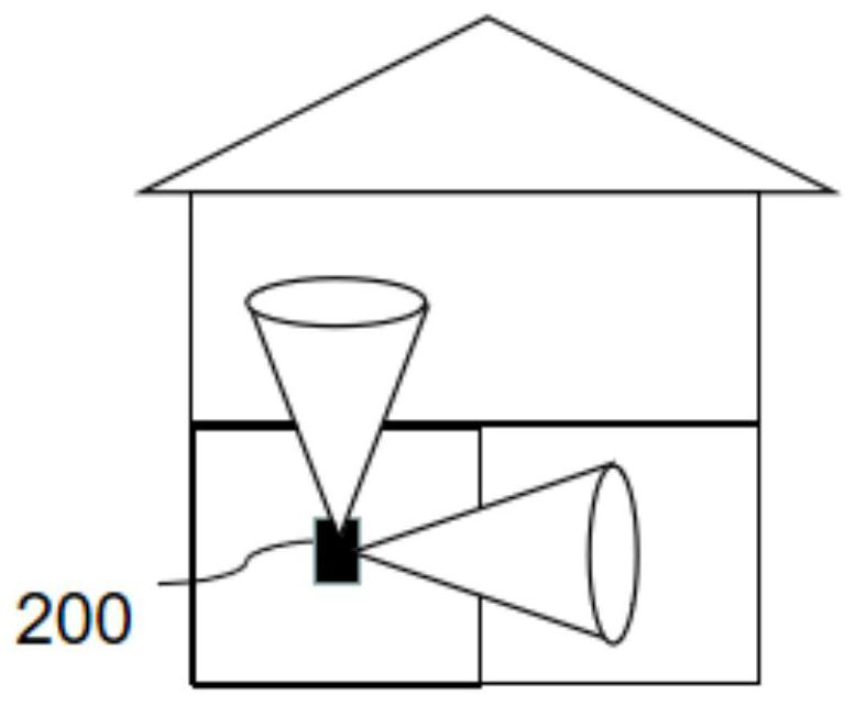
[0069] With the development of communication technology, the demand for wireless communication transmission in family scenarios is also increasing. like figure 1 As shown, in the wireless network device 200 provided by the present application, the internal antenna (not shown in the figure) has good horizontal omnidirectionality and vertical orientation, and can meet wireless communication requirements in different home scenarios. Usually, most ordinary family units are single-story units, and the coverage requirements of this unit type for home wireless communication are concentrated in horizontal omnidirectional, that is, different rooms in the same floor unit type can be covered by the wireless network device 200 . For some duplex or villa-type families, the vertical coverage function of the wireless network must be satisfied...


PUM


Abstract

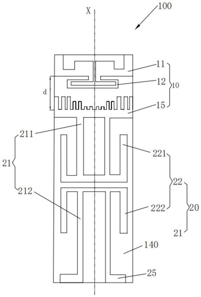
The invention discloses an antenna, which comprises a first antenna and a second antenna, the first antenna comprises a first radiation unit and a reflector, the reflector is located between the second antenna and the first radiation unit, the reflector comprises a connecting part and a tooth part, and the tooth part comprises a plurality of comb teeth which are arranged side by side and extend from the connecting part to the first radiation unit, gaps are arranged between the comb teeth, the tooth part comprises an outline facing the first radiation unit, each comb tooth comprises an end part facing the first radiation unit, the outline is formed by connecting all the end parts, and the outline comprises a concave part which is concave towards the connecting part. According to the antenna provided by the invention, the reflector which is composed of the plurality of comb teeth and is provided with the contour concave part is designed between the first radiation unit and the second antenna, so that the reflected path of the first radiation unit is increased, and the directional radiation performance of the first radiation unit is enhanced. The invention also provides an antenna module and wireless network equipment.

Description

technical field [0001] The present application relates to the communication field, in particular to an antenna, an antenna module and a wireless network device. Background technique [0002] The specifications of home network wireless communication products are developing very fast from 2*2, 4*4 to 8*8, and the frequency bands have also developed from 2G, 5G to 6G, and even continue to expand in the millimeter wave frequency band, but this is limited by product design and user requirements. Due to the limitations of habits and scenarios, the size of wireless devices in the home network cannot be infinitely increased. Therefore, how to achieve high-specification design under the existing product space conditions and realize the built-in integration of more high-performance antennas with little mutual influence has become very urgent. Design requirements, especially the new requirements of the upcoming 6G frequency band, for N*N MIMO design means that the number of antennas an...

Claims


Application Information

Patent Timeline
IPC IPC(8): H01Q1/36H01Q5/20H01Q15/14H01Q21/24
CPCH01Q1/36H01Q5/20H01Q15/14H01Q21/24H01Q9/285H01Q15/142H01Q21/28H01Q19/13H01Q15/16H01Q1/38H01Q19/17H01Q21/08
Inventor 邵金进武东伟石操
Owner HUAWEI TECH CO LTD
Learn More