
Brushless DC motor with built-in controller

A DC motor and controller technology, applied in the field of motors, can solve the problems of large equipment space, difficult automatic production, difficult automatic assembly, etc.

Active Publication Date: 2021-07-20
ZHEJIANG LEGE INTELLIGENT DRIVE TECH CO LTD
View PDF9 Cites 2 Cited by
  • Summary
  • Abstract
  • Description
  • Claims
  • Application Information

AI Technical Summary

Problems solved by technology

[0004] However, the brushless DC motor with a built-in controller in the prior art still has the following disadvantages: the controller is a circular plate with a large diameter, which occupies a large area in the radial direction, resulting in a large radial area of ​​the motor, and takes up a large space for equipment after the motor is installed.
All control components are in one chamber, poor heat dissipation
The controller needs to be directly fastened by multiple screws, which is not stable enough and takes up a lot of working area of ​​the controller panel
In addition, the coils of brushless DC motors in the prior art are all bound with cable ties and then cured with glue to insulate and fix with the insulating frame. The binding and glue curing process is cumbersome, the production cycle of each motor is relatively long, and the labor cost is relatively High, the material cost of binding wire and glue is relatively high, the production efficiency is relatively low, the defective rate of the stator is relatively high, and it is difficult to automate assembly, that is, it is difficult to automate production

Method used


Image

  • Brushless DC motor with built-in controller
  • Brushless DC motor with built-in controller
  • Brushless DC motor with built-in controller

Examples


Embodiment Construction

[0041] The specific embodiments of the present invention will be further described below in conjunction with the accompanying drawings. What needs to be declared here is that the descriptions of these specific implementations are used to help understand the present invention, but are not intended to limit the present invention. In addition, the technical features involved in the various specific embodiments of the present invention described below may be combined with each other as long as they do not constitute conflicts with each other.

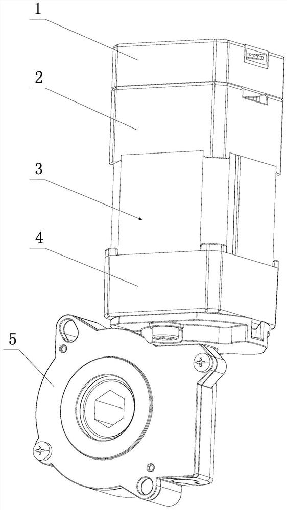
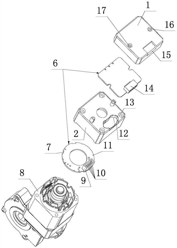
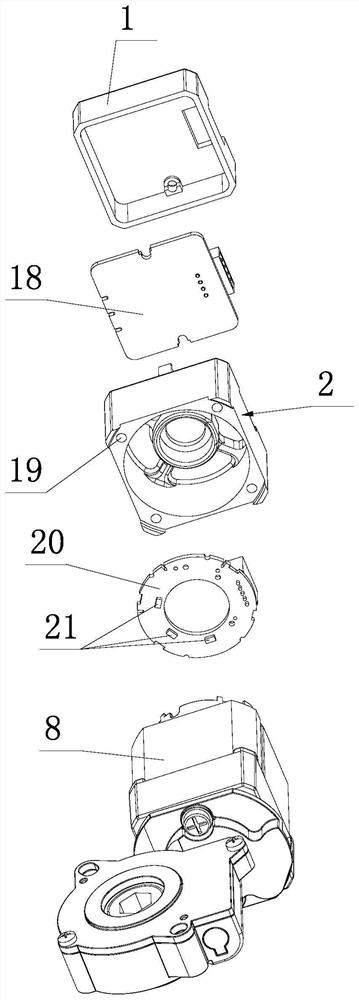
[0042] Such as figure 1 , figure 2 , image 3 , Figure 4 , Figure 5 , Image 6 , Figure 7 , Figure 8 , Figure 9 , Figure 10 , 15 shown.

[0043] The brushless DC motor with a built-in controller of the present invention includes a controller casing, a controller 6 , an end cover 4 and a stator 3 . The lower end of the end cover 4 is a worm gear output mechanism 5 . The stator 3 includes an iron core 8 , an insulating fra...


PUM


Abstract

The invention discloses a controller panel which comprises an annular Hall plate arranged in a first controller housing and a rectangular controller panel arranged in a second controller housing. The annular Hall plate is radially clamped and axially limited at the outer end part of the first circular insulating framework; the first controller housing is fastened with the iron core and the end cover through a plurality of screw rods; the two sides of the top of the first controller housing are each provided with a first protruding column which is provided with a threaded hole and extends vertically, the inner surface of a top plate of the second controller housing is provided with second protruding columns which correspond to the first protruding columns in position, are provided with through holes and extend vertically, and the end faces of the first protruding columns and the end faces of the second protruding columns are each provided with a step embedded with a rectangular controller panel. The two sides of the rectangular controller panel are provided with notches which are limited with the protruding columns in the radial direction. Two screws penetrate through the corresponding through holes to be screwed into the corresponding threaded holes so as to press the rectangular controller panel. The radial area of the controller panel and the motor is reduced, the controller panel is stable and reliable in fastening, and the heat dissipation effect of the controller is good.

Description

technical field [0001] The invention relates to the technical field of motors, in particular to a brushless DC motor with a built-in controller. Background technique [0002] Brushless DC motors are simply referred to as brushless motors. In recent years, with the increasing maturity and perfection of technology, brushless motors have been widely used in aircraft models, medical equipment, household appliances, office automation and other fields. [0003] The controllers of the early brushless DC motors were all external, which took up a lot of space, and the cost of materials such as wire harnesses was relatively high. In recent years, the built-in controller of the brushless DC motor has been gradually promoted. Compared with the external controller, the built-in controller or called the built-in controller has relatively low requirements for space layout, which reduces some materials and components such as wiring harnesses, and relatively reduces the cost. Product produ...

Claims


Application Information

Patent Timeline
Patent Type & Authority Applications(China)
IPC IPC(8): H02K5/04H02K11/215H02K3/32H02K11/30H02K5/22H02K7/116
CPCH02K5/04H02K11/215H02K3/32H02K11/30H02K5/225H02K7/1166
Inventor 项乐宏赵宏江鲍达
Owner ZHEJIANG LEGE INTELLIGENT DRIVE TECH CO LTD
Learn More