Supercharge Your Innovation With Domain-Expert AI Agents!

Boost converter

A technology of boost converters and switches, which is applied in high-efficiency power electronic conversion, instruments, and output power conversion devices, etc., can solve problems such as power consumption and lower output efficiency of boost converters.

Inactive Publication Date: 2021-07-20
ACER INC
View PDF1 Cites 0 Cited by
  • Summary
  • Abstract
  • Description
  • Claims
  • Application Information

AI Technical Summary

Problems solved by technology

This reverse inductor current will cause power consumption in the form of heat energy (hereinafter referred to as "heat consumption"), and at the same time cause the output efficiency of the boost converter to decrease

Method used


Image

  • Boost converter
  • Boost converter
  • Boost converter

Examples


Embodiment Construction

[0048] In order to make the purpose, features and advantages of the present invention more comprehensible, specific embodiments of the present invention are listed below and described in detail with accompanying drawings.

[0049] Certain terms are used in the description and claims to refer to particular elements. Those skilled in the art should understand that hardware manufacturers may use different terms to refer to the same component. The specification and claims do not use the difference in name as a way to distinguish components, but use the difference in function of components as a criterion for distinguishing. The words "comprising" and "comprising" mentioned throughout the specification and claims are open-ended terms, so they should be interpreted as "including but not limited to". The term "approximately" means that within an acceptable error range, those skilled in the art can solve the technical problem within a certain error range and achieve the basic technica...


PUM


Abstract

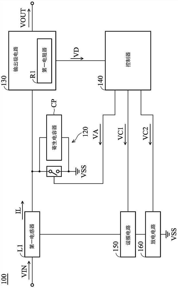
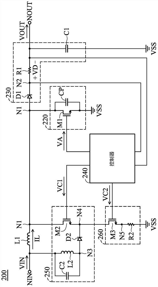
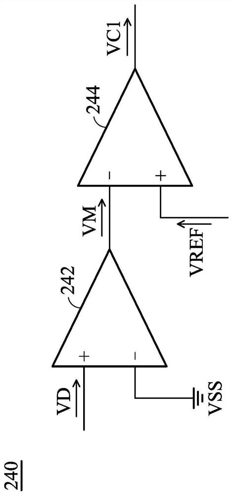
A boost converter includes a first inductor, a power switcher, an output stage circuit, a controller, a resonant circuit, and a discharge circuit. The first inductor is used for receiving an input potential. The power switch includes a parasitic capacitor. The output stage circuit comprises a first resistor, wherein the output stage circuit is used for generating an output potential. The controller detects a resistance potential of the first resistor and generates a clock potential, a first control potential and a second control potential according to the resistance potential. The resonant circuit is coupled to the first inductor and is selectively enabled or disabled according to a first control potential. When the resonant circuit is enabled, the resonant circuit resonates with the first inductor and the parasitic capacitor to adjust an inductive current through the first inductor.

Description

technical field [0001] The invention relates to a boost converter, in particular to a boost converter with high output efficiency. Background technique [0002] In a traditional boost converter, its boost inductor tends to resonate with the parasitic capacitors of the power switcher and generate a reverse inductor current. This reverse inductor current will cause power consumption in the form of heat (hereinafter referred to as "heat consumption"), and at the same time cause the output efficiency of the boost converter to decrease. In view of this, it is necessary to propose a new solution to overcome the difficulties faced by the existing technologies. Contents of the invention [0003] In a preferred embodiment, the present invention provides a boost converter, comprising: a first inductor receiving an input potential; a power switch including a parasitic capacitor, wherein the power switch is based on the clock potential To determine whether the first inductor is coup...

Claims


Application Information

Patent Timeline
Patent Type & Authority Applications(China)
IPC IPC(8): H02M3/156
CPCH02M3/156Y02B70/10
Inventor 詹子增
Owner ACER INC
Features
  • R&D
  • Intellectual Property
  • Life Sciences
  • Materials
  • Tech Scout
  • Unparalleled Data Quality
  • Higher Quality Content
  • 60% Fewer Hallucinations
Learn More