Driver circuit for P type power MOS switch tube

A technology for driving circuits and switching tubes, applied in electronic switches, electrical components, pulse technology, etc., can solve the problems of power loss, the inability of P-type power MOS tubes to turn on and off quickly, save energy, improve switching efficiency, The effect of improving efficiency and energy utilization

Inactive Publication Date: 2009-01-28
SHANGHAI INST OF SPACE POWER SOURCES
View PDF0 Cites 26 Cited by
  • Summary
  • Abstract
  • Description
  • Claims
  • Application Information

AI Technical Summary

Problems solved by technology

[0004] In order to solve the problems that the P-type power MOS tube cannot be quickly turned on and off, and the power loss in the switching process, the object of the present invention is to provide a P-type power MOS switch tube drive circuit. In addition to applying a certain amount of negative pulse voltage, a certain amount of driving current is applied to the gate of the P-t

Method used


Image

  • Driver circuit for P type power MOS switch tube
  • Driver circuit for P type power MOS switch tube
  • Driver circuit for P type power MOS switch tube

Examples


Embodiment Construction

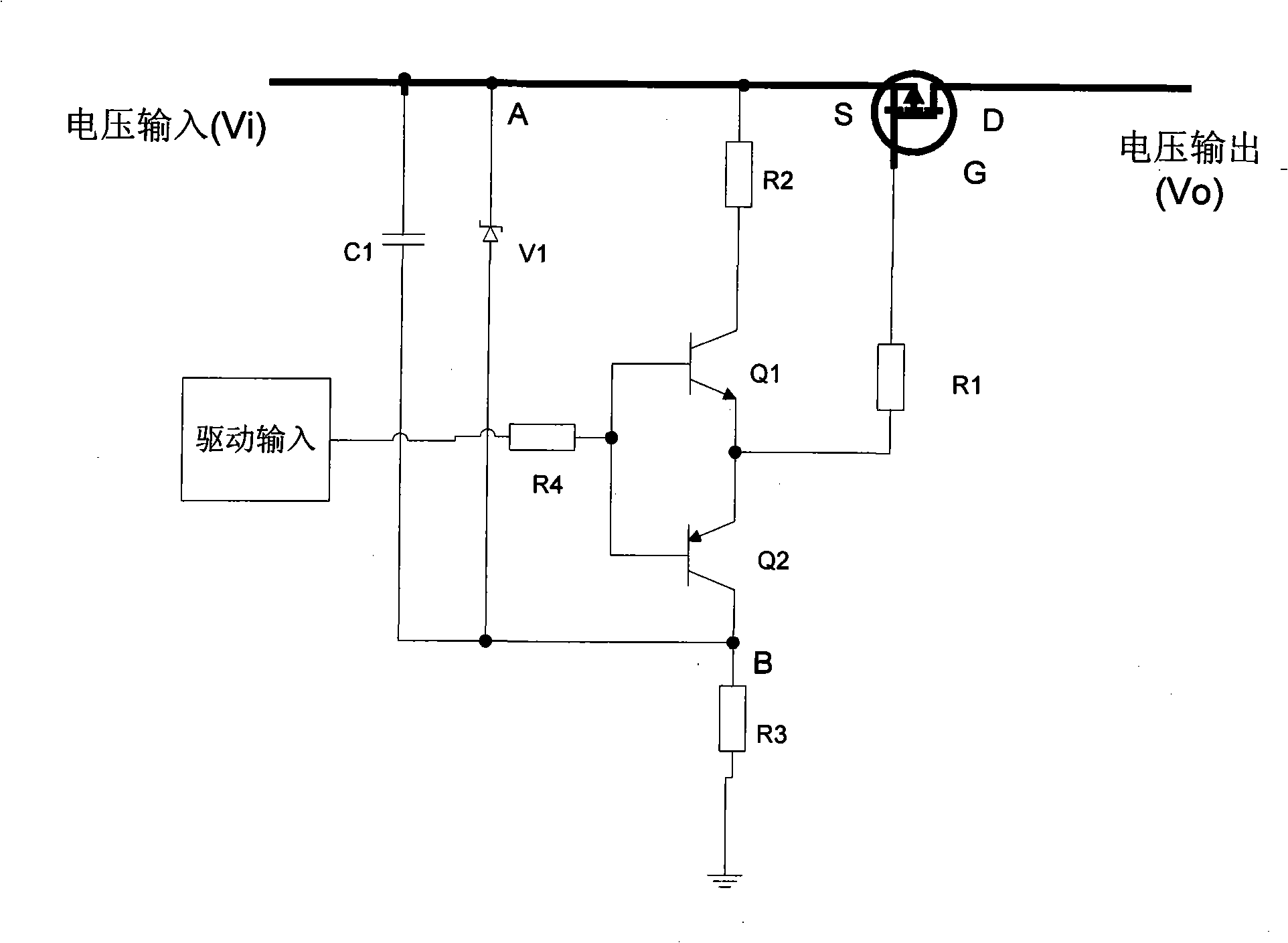
[0014] The drive circuit of the P-type power MOS switching tube of the present invention uses a floating voltage control and a push-pull circuit driving mode to switch and control the P-type power MOS tube, thereby improving the dynamic characteristics and switching efficiency of the P-type power MOS tube. It provides a charge output circuit and a floating voltage for the gate of the P-type MOS transistor to be turned off through the circuit characteristics of the capacitor, thereby reducing the control complexity of the P-type power MOS transistor drive circuit.

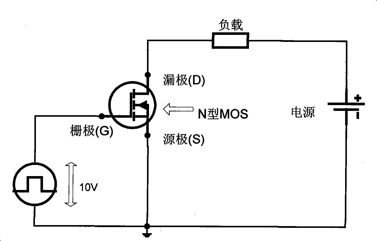
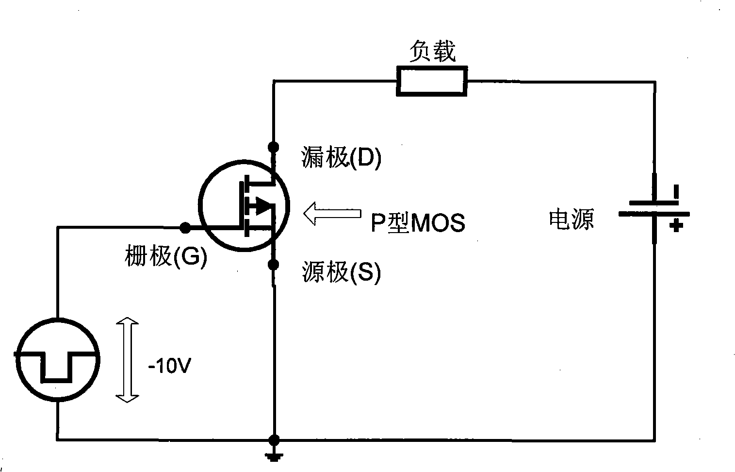
[0015] Power MOS tubes are divided into N-type power MOS tubes and P-type power MOS tubes. N-type power MOS tubes are suitable for positive power supply. P-type power MOS tube is suitable for negative power supply.

[0016] figure 1 It is the working electrical schematic diagram of the N-type power MOS tube; the load is connected between the positive pole of the power supply and the drain of the MOS tube. A drivin...


PUM


Abstract

The invention discloses a drive circuit for a P type power MOS switch tube. A push-pull drive circuit and a floating voltage division circuit are connected between a source electrode and a grid electrode of the P type power MOS switch tube. The push-pull drive circuit rapidly controls the charging and discharging of a parasitic capacitor inside the P type power MOS tube by transient current generated when triodes Q1 and Q2 are in alternates; and the floating voltage division circuit provides a stable voltage value of a negative pulse grid source for the P type power MOS tube, thereby improving the dynamic property of the P type power MOS tube and reducing the switch loss of the P type power MOS tube as well as having the advantages of stability, reliability, flexible control and low energy consumption, and the like.

Description

technical field [0001] The invention relates to the application of electronic components, in particular to a driving circuit of a P-type power MOS switch tube. Background technique [0002] In the past ten years, high-power MOS tubes have not only triggered a revolution in power supply and energy control technology, but also greatly promoted the development of the electronics industry. Due to the high-speed switching speed of the power MOS tube, the switching frequency of the power control system can be made very high, so that the volume of the power control system can be further reduced, thereby obtaining the best quality-to-power output ratio. Especially for P-type power MOS tubes, in aerospace and other fields that have special requirements for power supply control, using P-type power MOS tubes as the main switch control device is not only the best choice, but may also be the only choice. Especially in the process of charging the battery on the star, because the voltage ...

Claims


Application Information

Patent Timeline
IPC IPC(8): H03K17/04H03K17/687
Inventor 沈昂刘咏晖
Owner SHANGHAI INST OF SPACE POWER SOURCES
Why Eureka
Try Eureka