Drill bit connecting structure of fixed-handle drill

A connection structure and drill bit technology, applied in drilling/drilling equipment, drill repair, drilling tool accessories, etc., can solve the problems of different chucks, affecting work efficiency, loosening, etc., to achieve simple and convenient assembly operation, stable and reliable connection , the effect of prolonging the service life

Pending Publication Date: 2021-07-23
JIANGSU TIANGONG PRECISION TOOLS CO LTD
View PDF1 Cites 0 Cited by
  • Summary
  • Abstract
  • Description
  • Claims
  • Application Information

AI Technical Summary

Problems solved by technology

[0002] Hole cutting refers to the method of using related tools to remove the excess material of the machined parts to form the required holes. Ordinary twist drills have been used for nearly a hundred years under various conditions of use. During the use, it gradually exposed some defects that need to be improved. Traditional Ordinary twist drills have two types of straight shank and tapered shank. The main problems in use are as follows: drills of different specifications require different collets, resulting in a lot of tooling and increasing the difficulty of management. Therefore, it is necessary to develop a fixed shank drill. seems necessary
[0003] In the traditional technology, drill bits with different diameters are inserted into the drill shank with a fixed diameter, but in the traditional structure, after the drill bit is inserted into the drill shank, the drill shank and the drill bit are connected by bonding or riveting with glue. Fixing, such as in CN 206009943 U, which has a mounting hole with a diameter larger than the cylindrical tail of the drill bit at the center of the drill shank, then inserts the tail of the drill bit into the mounting hole, and then fills the gap between the tail of the drill bit and the mounting hole Hold the adhesive layer for fixing, the connection of this structure is too simple, and because the rod of the drill bit is a smooth cylindrical shape, it is easy to cause slipping or loosening, which affects work efficiency

Method used


Image

  • Drill bit connecting structure of fixed-handle drill
  • Drill bit connecting structure of fixed-handle drill
  • Drill bit connecting structure of fixed-handle drill

Examples


Embodiment Construction

[0020] In order to deepen the understanding of the present invention, the present invention will be further described in detail below with reference to the accompanying drawings and embodiments. The embodiments are only used to explain the present invention and do not limit the protection scope of the present invention.

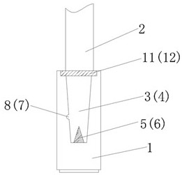
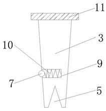
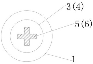
[0021] As shown in the figure, the present invention provides a fixed-shank drill bit connection structure, which adopts a fixed-shank design, including a drill shank 1 with a fixed diameter and a drill body 2 with different diameters, and the diameter of the drill shank is uniformly 12.7 mm, drill shank 1 and drill body 2 are made of cobalt-containing high-performance high-speed steel, which has higher hardness than ordinary high-speed steel, higher red hardness, more wear-resistant, longer life, and adopts full grinding production process , The precision of the product is higher, and the surface is coated with PDV, which further improves its wear resistance ...


PUM


Abstract

The invention relates to a drill bit connecting structure of a fixed-handle drill. The drill bit connecting structure comprises a drill handle and a drill body, wherein a connecting portion is arranged at the bottom end of the drill body; a connecting groove corresponding to the connecting portion is formed in the drill handle; the connecting portion is inserted into the connecting groove; an inwards-concave limiting groove is formed in the bottom of the connecting portion; a convex block matched with the limiting groove in shape is arranged at the bottom of the connecting groove; a positioning mechanism is further arranged between the drill handle and the connecting portion; the positioning mechanism comprises a telescopic positioning steel ball arranged on one side of the connecting portion; and a positioning hole corresponding to the positioning steel ball is formed in the inner wall of the connecting groove.

Description

technical field [0001] The invention belongs to the field of cutting tools, and in particular relates to a connection structure of a fixed shank drill bit. Background technique [0002] Hole cutting refers to the method of using relevant tools to remove the excess material of the processed parts to form the required holes. The ordinary twist drill has been used for nearly a hundred years under various conditions of use. During the use process, it gradually exposes some defects that need to be improved. Traditional Ordinary twist drills have two types of straight shank and tapered shanks. The main problems in use are as follows: drills of different specifications require different chucks, resulting in a variety of tooling and increasing management difficulty. For this reason, the development of a fixed shank drill seems necessary. [0003] In the traditional technology, the drill bits of different diameters are inserted into the drill shank of a fixed diameter, but in the tr...

Claims


Application Information

Patent Timeline
Patent Type & Authority Applications(China)
IPC IPC(8): B23B51/00
CPCB23B51/00
Inventor 朱小坤何建国
Owner JIANGSU TIANGONG PRECISION TOOLS CO LTD
Why Eureka
Try Eureka