
Adjustable face-and-side cutter head and adjusting method

A technology of three-sided edge and milling cutter disc, which is applied in the field of mechanical processing, can solve the problems that are not conducive to ensuring the processing accuracy of products, is not conducive to production efficiency, and increases the cost of cutting tools, so as to save processing time, maximize efficiency, and improve production efficiency. Effect

Pending Publication Date: 2021-07-23
西安海纳精密机械有限公司
View PDF0 Cites 1 Cited by
  • Summary
  • Abstract
  • Description
  • Claims
  • Application Information

AI Technical Summary

Problems solved by technology

It is not conducive to improving production efficiency, nor is it conducive to ensuring the processing accuracy of products
For small and medium-sized enterprises, it will also increase the input cost of tools

Method used


Image

  • Adjustable face-and-side cutter head and adjusting method
  • Adjustable face-and-side cutter head and adjusting method
  • Adjustable face-and-side cutter head and adjusting method

Examples


Embodiment 1

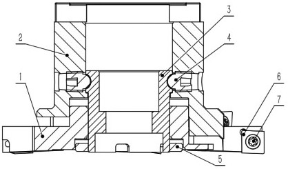
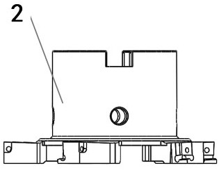
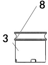
[0030] Embodiment 1: In combination with all the drawings; the adjustable three-sided edge milling cutter head is characterized in that the three-sided edge milling cutter head includes a fixed cutter head (2), and the fixed cutter head (2) contains a limit hole, which can also be limited The position locking screw (4) is pressed against the adjusting mandrel (3). The adjusting mandrel (3) contains a circle of arc-shaped grooves. The arc at the end of the limit locking screw (4) can fit the arc Groove, the adjustment mandrel can only rotate and cannot move up and down; the adjustable cutter head (1) is installed on the thread under the adjustment mandrel (3), and the relative position of the adjustable cutter head (1) can be adjusted by turning the adjustment mandrel (3) height; the lock nut (5) is ring-shaped, and the lock nut (5) is installed under the adjustment mandrel (3) to relatively lock the adjustable cutter head (1). The substantive technical effect and the realizati...

Embodiment 2

[0033] Embodiment 2: As a further improved solution or a side-by-side solution or an optional independent solution, the fixed cutterhead and the adjustable cutterhead adopt a structure in which the cutter position mounting surfaces are dislocated to achieve adjustment space. The substantive technical effect and the realization process of the technical solution here are as follows: the dislocation makes the adjustment convenient, and at the same time, the distribution is uniform.

Embodiment 3

[0034] Embodiment 3: As a further improved solution or a side-by-side solution or an optional independent solution, the knife position mounting surfaces of the fixed cutter head and the adjustable cutter head are each equipped with a blade (6) through a blade locking screw (7). The substantive technical effects and the realization process of the technical solution here are as follows: this embodiment provides a specific structure for fixing the blade, and similar realization structures are all within the scope of protection of this patent.


PUM


Abstract

The invention relates to the field of machining, in particular to an adjustable face-and-side cutter head and an adjusting method. The adjustable face-and-side cutter head can implement one-time machining of grooves with different widths under the condition of the same diameter, the machining time can be saved to the maximum extent by adjusting the groove widths, and the production efficiency is improved. In actual trial cut for machining, an adjustable three-sided blade can achieve the same milling effect as a traditional fixed-width three-sided blade, and the milling requirements for various groove widths can be met. Meanwhile, due to the fact that the width is adjustable, the economic effect that one cutter can be used instead of various face and side cutter heads is achieved. As the groove width can be adjusted, the efficiency can be maximized according to the design requirement of the actual groove width of the part. The adjustable three-sided blade changes the knowledge on milling with a traditional fixed three-sided blade, deep-groove milling is more easier and direct to carry out. The groove width can be adjusted at will, and meanwhile the machining precision and efficiency requirements of parts can be effectively met.

Description

technical field [0001] The invention relates to the field of mechanical processing, in particular to an adjustable three-sided edge milling cutter disc and an adjustment method. Background technique [0002] In the process of mechanical processing, as the design of parts becomes more and more complex, the requirements for cutting tools are also getting higher and higher. In CNC milling, there are more and more sealing grooves, deep grooves, relief grooves, and lightening grooves. , the requirements for processing also increase. Due to the limitation of the number of cutting tools in the machining center, when the groove width of the part is large, it has to be processed with a three-sided milling cutter with various blade widths, or a flexible method is used to use one knife to make way up and down for milling. To ensure the groove width. It is not conducive to improving production efficiency, and is also not conducive to ensuring the processing accuracy of products. For ...

Claims


Application Information

Patent Timeline
Patent Type & Authority Applications(China)
IPC IPC(8): B23C5/08B23C5/24B23C5/26B23Q3/14
CPCB23C5/08B23C5/26B23Q3/14B23C2210/16B23C5/24B23C5/2204
Inventor 陶亚辉
Owner 西安海纳精密机械有限公司
Learn More