
Groove milling, clamping and positioning device for spline shaft

A technology of positioning device and spline shaft, applied in the field of mechanical fixtures, can solve the problem of no fixtures and the like, and achieve the effects of stable clamping, convenient operation and simple structure

Inactive Publication Date: 2017-05-31
QIJIANG YONGYUE GEAR
View PDF7 Cites 0 Cited by
  • Summary
  • Abstract
  • Description
  • Claims
  • Application Information

AI Technical Summary

Problems solved by technology

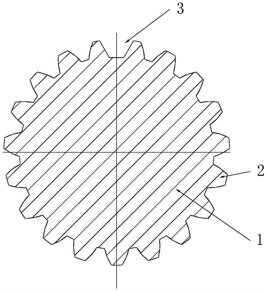
Due to the structural characteristics of the main shaft, there is no special tooling and fixture for processing the groove 3 in the prior art

Method used


Image

  • Groove milling, clamping and positioning device for spline shaft
  • Groove milling, clamping and positioning device for spline shaft

Examples


Embodiment Construction

[0014] The present invention will be further described below in conjunction with the accompanying drawings and specific embodiments, so that those skilled in the art can better understand the present invention and implement it, but the examples given are not intended to limit the present invention.

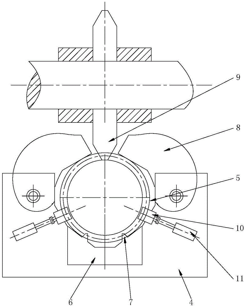
[0015] Such as figure 2 Shown is a schematic structural view of an embodiment of the spline shaft milling, clamping and positioning device of the present invention. The spline shaft milling groove clamping and positioning device of this embodiment includes a base 4, a clamping groove 5 is provided on the upper surface of the base 4, a positioning block 6 is provided at the bottom of the clamping groove 5, and the positioning Block 6 is provided with at least two spline teeth 2 limit fit and the tooth grooves that need to be further milled grooves are aligned with the milling cutter 9, and the two sides of the clamping groove 5 are respectively provided with The spline shaft body...


PUM


Abstract

The invention discloses a groove milling, clamping and positioning device for a spline shaft. The groove milling, clamping and positioning device comprises a base. A clamping groove is formed in the upper surface of the base. A positioning block is arranged at the bottom of the clamping groove. The positioning block is provided with a tooth groove matched with at least two spline teeth in a limited manner and needing to be further milled, and positioning teeth aligned with a milling tool. Each of the two sides of the clamping groove is provided with a pressing mechanism used for pressing and fixing the spline shaft body to the positioning block, and a meshing positioning mechanism used for being engaged with spline teeth. Each meshing positioning mechanism comprises a meshing block and a meshing air cylinder used for driving the meshing block to move in the radial direction of the spline shaft body, wherein the meshing block is provided with meshing teeth engaged with the spline teeth. According to the groove milling, clamping and positioning device for the spline shaft, a main shaft provided with the spline teeth can be clamped and positioned, and the requirement for milling machining of grooves is met.

Description

technical field [0001] The invention belongs to the technical field of mechanical fixtures, and in particular relates to a spline shaft milling groove clamping and positioning device. Background technique [0002] Such as figure 1 Shown is a radial cross-sectional view of an existing spline shaft. The main shaft includes a spline shaft body 1 , spline teeth 2 are provided on the peripheral wall of the spline shaft body 1 , and a widened groove 3 is further provided at the tooth groove between the two spline teeth 2 . The spline teeth 2 may be involute spline teeth, or other structures of spline teeth. In the prior art, in order to meet the position requirements between the groove 3 and the spline teeth 2, it is generally necessary to process the spline teeth 2 on the spline shaft body 1, and then process the groove between two of the spline teeth 2. Due to the structural characteristics of the main shaft, there is no special tooling and fixture for machining the groove 3 ...

Claims


Application Information

Patent Timeline
IPC IPC(8): B23Q3/08
CPCB23Q3/08B23Q3/062B23Q2703/04
Inventor 张集胜崔家川
Owner QIJIANG YONGYUE GEAR
Learn More