Supercharge Your Innovation With Domain-Expert AI Agents!

Positioning device and method based on plastic pipe cutting

A technology of positioning device and plastic pipe, applied in the field of plastic pipe processing, can solve the problems of inaccurate cutting, large error, easy shaking of the plastic pipe, etc., and achieve the effect of avoiding the knife and cutting quickly.

Inactive Publication Date: 2021-07-23
安徽金利塑业股份有限公司
View PDF0 Cites 1 Cited by
  • Summary
  • Abstract
  • Description
  • Claims
  • Application Information

AI Technical Summary

Problems solved by technology

[0002] Plastic pipes are used for water supply system piping, drainage, exhaust and sewage sanitary pipes, underground drainage pipe systems, rainwater pipes, and threading pipes for wire installation in housing construction; when processing plastic pipes, they need to be cut into different lengths , the operator generally presses the plastic pipe with his hand, and then cuts. When the plastic pipe is held down by hand, the plastic pipe is easy to shake, resulting in inaccurate cutting and large errors. Therefore, a positioning device based on plastic pipe cutting is designed here. Positioning method, in order to solve the above problems

Method used


Image

  • Positioning device and method based on plastic pipe cutting
  • Positioning device and method based on plastic pipe cutting
  • Positioning device and method based on plastic pipe cutting

Examples


Embodiment 1

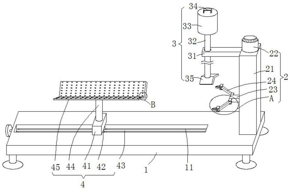
[0027] see Figure 1-4 , this embodiment provides a positioning device and a positioning method based on plastic pipe cutting, including a base 1 and a transmission mechanism 2, the upper end of the base 1 is provided with a support mechanism 4 that can move horizontally to adjust the support position, by moving horizontally along the upper end of the base 1 Adjust the position of the support mechanism 4, and then use the support mechanism 4 to support the plastic pipe to be cut. The transmission mechanism 2 is arranged on the upper right side of the base 1, and the left side of the transmission mechanism 2 is provided with a press for rolling and pressing the plastic pipe. Combining mechanism 3, using pressing mechanism 3 to press the upper end of the plastic pipe, can cooperate with supporting mechanism 4 to position and clamp the plastic pipe to be cut, and use transmission mechanism 2 to drive the plastic pipe to rotate between supporting mechanism 4 and pressing mechanism ...

Embodiment 2

[0036] see Figure 1-4 , made further improvement on the basis of embodiment 1:

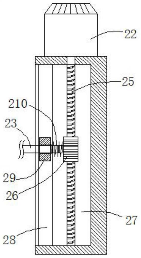
[0037] In order to solve the problem of how to ensure that the worm gear 25 and the worm screw 26 are meshed together in real time, the outer wall of the extension beam 23 is slidably adjusted with a spring 210 between the limit slider 29 and the worm screw 26, and the spring 210 is used to connect the limit slider 29 and the worm screw 26. 26 can be jacked up in real time, and the turbine 26 can be jacked up to the worm screw 25 side, so as to ensure that the turbine 25 and the worm screw 26 are meshed together in real time to realize the transmission of power.

[0038] In order to further solve the problem of how to avoid the plastic pipe placed on the V-shaped support block 45 from shaking during the cutting process, the top of the suspension rod 32 is fixedly provided with a counterweight column 33, and the inverted V-shaped pressing plate 35 is matched by the counterweight column 33. Heavy,...


PUM


Abstract

The invention discloses a positioning device and method based on plastic pipe cutting, and relates to the technical field of plastic pipe machining. The positioning device comprises a base and a transmission mechanism, wherein the transmission mechanism comprises a stand column, a worm, a turbine, a limiting sliding block and an extending cross beam, the stand column is vertically fixed to the middle section of the right side of the upper end of the base, the worm is rotatably inserted between the upper side wall and the lower side wall in a mounting groove, the limiting sliding block is slidably clamped in two limiting clamping grooves, the extending cross beam rotatably penetrates through the limiting sliding block and extends to the left side of the stand column, two hinge rods are symmetrically hinged to the left end of the extending cross beam, hinge seats are hinged to the tips of the hinge rods, two clamping blocks of a V-shaped structure are symmetrically arranged at the end, away from the hinge rods, of the hinge seats, the right end of the extending cross beam is fixedly connected with a turbine, and the turbine is meshed with the worm. According to the positioning device and method based on plastic pipe cutting, to-be-cut plastic pipes of different sizes are positioned and clamped through a supporting mechanism and a pressing mechanism, then the clamped and positioned plastic pipes can be driven by the transmission mechanism to rotate, and cutting equipment can conveniently cut the plastic pipes.

Description

technical field [0001] The invention relates to the technical field of plastic pipe processing, in particular to a positioning device and a positioning method based on plastic pipe cutting. Background technique [0002] Plastic pipes are used for water supply system piping, drainage, exhaust and sewage sanitary pipes, underground drainage pipe systems, rainwater pipes, and threading pipes for wire installation in housing construction; when processing plastic pipes, they need to be cut into different lengths , the operator generally presses the plastic pipe with his hand, and then cuts. When the plastic pipe is held down by hand, the plastic pipe is easy to shake, resulting in inaccurate cutting and large errors. Therefore, a positioning device based on plastic pipe cutting is designed here. positioning method in order to solve the above problems. Contents of the invention [0003] The purpose of the present invention is to provide a positioning device and a positioning me...

Claims


Application Information

Patent Timeline
Patent Type & Authority Applications(China)
IPC IPC(8): B26D7/02
CPCB26D7/02B26D2007/013
Inventor 胡海滨
Owner 安徽金利塑业股份有限公司
Features
  • R&D
  • Intellectual Property
  • Life Sciences
  • Materials
  • Tech Scout
  • Unparalleled Data Quality
  • Higher Quality Content
  • 60% Fewer Hallucinations
Learn More