
Machine vision automatic trolley

An automatic trolley and machine vision technology, which is applied to conveyors, conveyor objects, household appliances, etc., can solve problems such as soup spills, customers mistaken dishes, troubles, etc., and achieve the effect of preventing spills and preventing dishes from spilling

Active Publication Date: 2021-07-23
ZHENGZHOU RAILWAY VOCATIONAL & TECH COLLEGE
View PDF6 Cites 0 Cited by
  • Summary
  • Abstract
  • Description
  • Claims
  • Application Information

AI Technical Summary

Problems solved by technology

[0004]First, in modern restaurants, machine vision automatic trolleys will be used to serve dishes instead of manual labor, but the existing automatic trolleys only deliver the dishes to the table, and Customers need to manually remove the dishes from the trolley, which is cumbersome and prone to mistakes by customers
[0005]Second, the space in the restaurant is narrow and the flow of people is crowded. The existing car turns through the steering mechanism like a car, which takes up a lot of space during the turning process and is inconvenient
[0006]Third, during the delivery of food by the automatic trolley, the user may suddenly block the front of the moving path. soup spill situation

Method used


Image

  • Machine vision automatic trolley
  • Machine vision automatic trolley
  • Machine vision automatic trolley

Examples


Embodiment 1

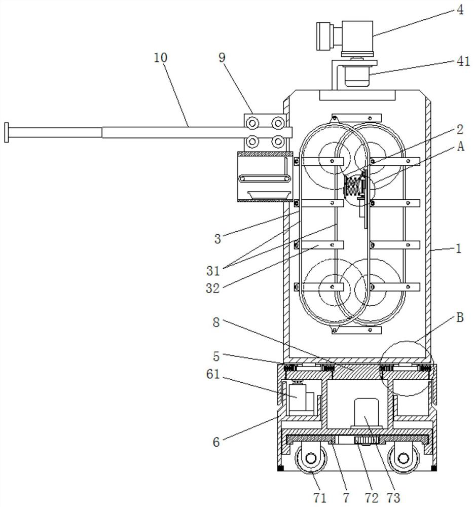
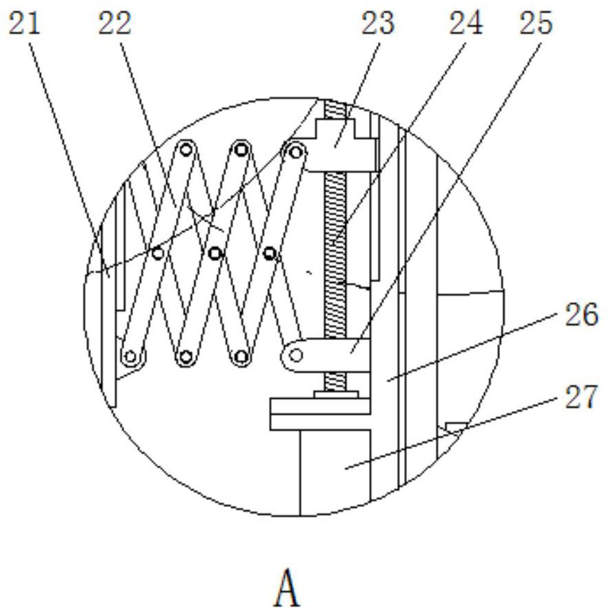
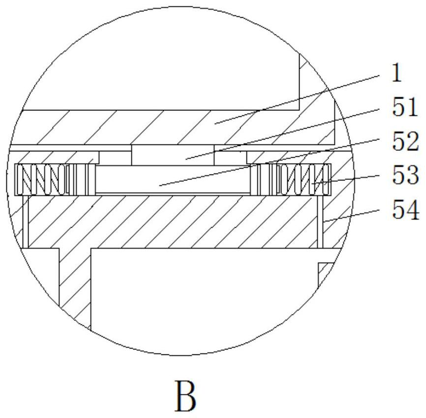
[0039] The present invention provides a kind of machine vision automatic trolley here through improvement, as Figure 1-Figure 10 As shown, a machine vision automatic trolley includes a frame 1 with a horizontal lifting mechanism 3 in the middle of the frame 1. The horizontal lifting mechanism 3 includes 2 chain belt conveyors 31, and the 2 chain belt conveyors 31 are asymmetrically arranged on the machine. On the both side walls of the frame 1, and between the two chain belt conveyors 31, several equidistantly distributed platens 32 are hinged, and a track frame 10 is arranged on the top of one side of the frame 1, and the track frame 10 is movably connected with Transmission mechanism 9, the position of transmission mechanism 9 corresponds to the position of platen 32, the bottom of frame 1 is connected with base 8 through emergency stop buffer mechanism 5, and the top of frame 1 is provided with vision sensor 4.

[0040] Through the mutual cooperation of the horizontal lift...

Embodiment 2

[0050] The present invention provides a kind of machine vision automatic trolley here through improvement, as Figure 1-Figure 10 As shown, a machine vision automatic trolley includes a frame 1 with a horizontal lifting mechanism 3 in the middle of the frame 1. The horizontal lifting mechanism 3 includes 2 chain belt conveyors 31, and the 2 chain belt conveyors 31 are asymmetrically arranged on the machine. On the both side walls of the frame 1, and between the two chain belt conveyors 31, several equidistantly distributed platens 32 are hinged, and a track frame 10 is arranged on the top of one side of the frame 1, and the track frame 10 is movably connected with Transmission mechanism 9, the position of transmission mechanism 9 corresponds to the position of platen 32, the bottom of frame 1 is connected with base 8 through emergency stop buffer mechanism 5, and the top of frame 1 is provided with vision sensor 4.

[0051] Through the mutual cooperation of the horizontal lift...


PUM


Abstract

The invention discloses a machine vision automatic trolley. The machine vision automatic trolley comprises a rack, wherein a horizontal lifting mechanism is arranged in the middle of the rack and comprises two chain belt conveyors, the two chain belt conveyors are asymmetrically arranged on the two side walls of the rack, a plurality of platens distributed at equal intervals are hinged between the two chain belt conveyors, a rail frame is arranged at the top of one side of the rack, a conveying mechanism is movably connected to the rail frame, the position of the conveying mechanism corresponds to the positions of the platens, the bottom of the rack is connected with a base through an emergency stop buffering mechanism, and a visual sensor is arranged at the top of the rack. According to the invention, through the mutual cooperation of the horizontal lifting mechanism and the conveying mechanism, dishes can be directly conveyed to a dining table of a customer, the customer does not need to take the dishes manually, convenience is brought to the customer, the situation that the customer takes the dishes mistakenly actively can be prevented, and through the design of the emergency stop buffering mechanism, the inertia generated when the trolley is braked suddenly can be buffered, and the situation that dishes are splashed is prevented.

Description

technical field [0001] The invention relates to the technical field of machine vision automatic trolleys, in particular to a machine vision automatic trolley. Background technique [0002] Machine vision is a rapidly developing branch of artificial intelligence. Simply put, machine vision is the use of machines instead of human eyes for measurement and judgment. The machine vision system converts the captured target into an image signal through the machine vision product (that is, the image capture device, which is divided into CMOS and CCD), and transmits it to a dedicated image processing system to obtain the shape information of the captured target. According to the pixel distribution and Information such as brightness and color is converted into digital signals; the image system performs various operations on these signals to extract the characteristics of the target, and then controls the on-site equipment actions according to the results of the discrimination. The un...

Claims


Application Information

Patent Timeline
Patent Type & Authority Applications(China)
IPC IPC(8): B65G17/12B65G17/34B65G47/82B65G41/00A47G23/08
CPCB65G17/123B65G17/345B65G47/82B65G41/008A47G23/08
Inventor 王子铭马帅金光张少辉张培李帆
Owner ZHENGZHOU RAILWAY VOCATIONAL & TECH COLLEGE
Learn More