Eureka AIR delivers breakthrough ideas for toughest innovation challenges, trusted by R&D personnel around the world.

High-strength building concrete column pouring construction method

A concrete column and construction method technology, which is applied in the direction of construction, building structure, and on-site preparation of building components, can solve problems such as inclination of the support formwork, damage at the edge of the concrete column, and cracking on the circumferential surface of the concrete column. The effect of avoiding cracking and avoiding damage

Inactive Publication Date: 2021-07-23
郭良红
View PDF7 Cites 1 Cited by
  • Summary
  • Abstract
  • Description
  • Claims
  • Application Information

AI Technical Summary

Problems solved by technology

[0005] The invention provides a construction method for pouring high-strength building concrete columns, and aims to solve the following problems existing in the concrete column pouring construction process at present: (1) when the concrete columns are poured and constructed, the concrete columns will be degraded during the hydration process A large amount of heat is generated, and the support formwork is difficult to effectively dissipate heat from the concrete column, which may easily lead to cracks on the circumferential surface of the concrete column and adversely affect the surface quality of the concrete column; , when disassembling this kind of support formwork, it is necessary to use tools to lift the support formwork. In the process, the tool is easy to cause damage to the edge of the concrete column, and the edge of the support formwork is also easy to scratch the circumferential surface of the concrete column; (3) During the process of pouring concrete columns, the concrete will exert pressure on the support formwork, and the pressure will gradually increase from top to bottom, and the support formwork will tilt under the pressure, resulting in irregular shapes of the outer circumference of the poured concrete column

Method used


Image

  • High-strength building concrete column pouring construction method
  • High-strength building concrete column pouring construction method
  • High-strength building concrete column pouring construction method

Examples


Embodiment Construction

[0042] The embodiments of the present invention will be described in detail below with reference to the accompanying drawings, but the present invention can be implemented in many different ways defined and covered by the claims.

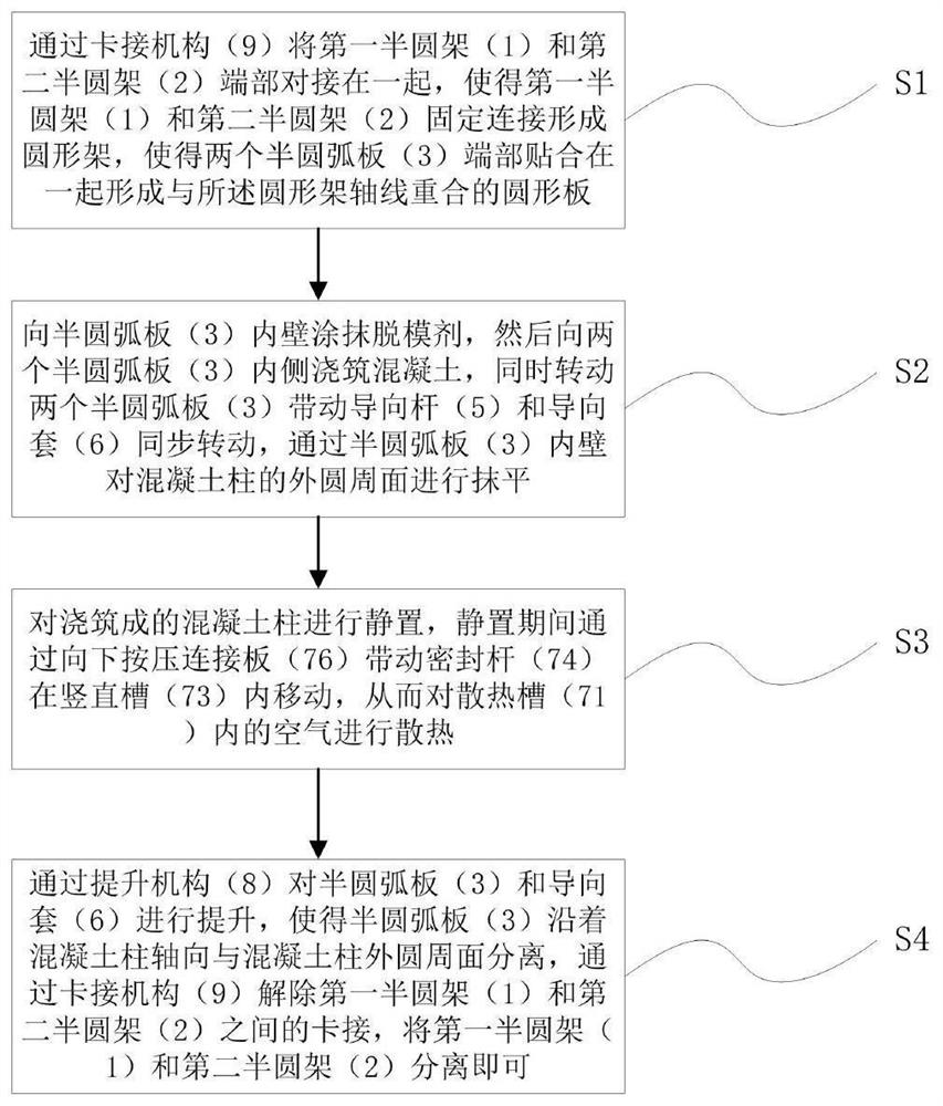
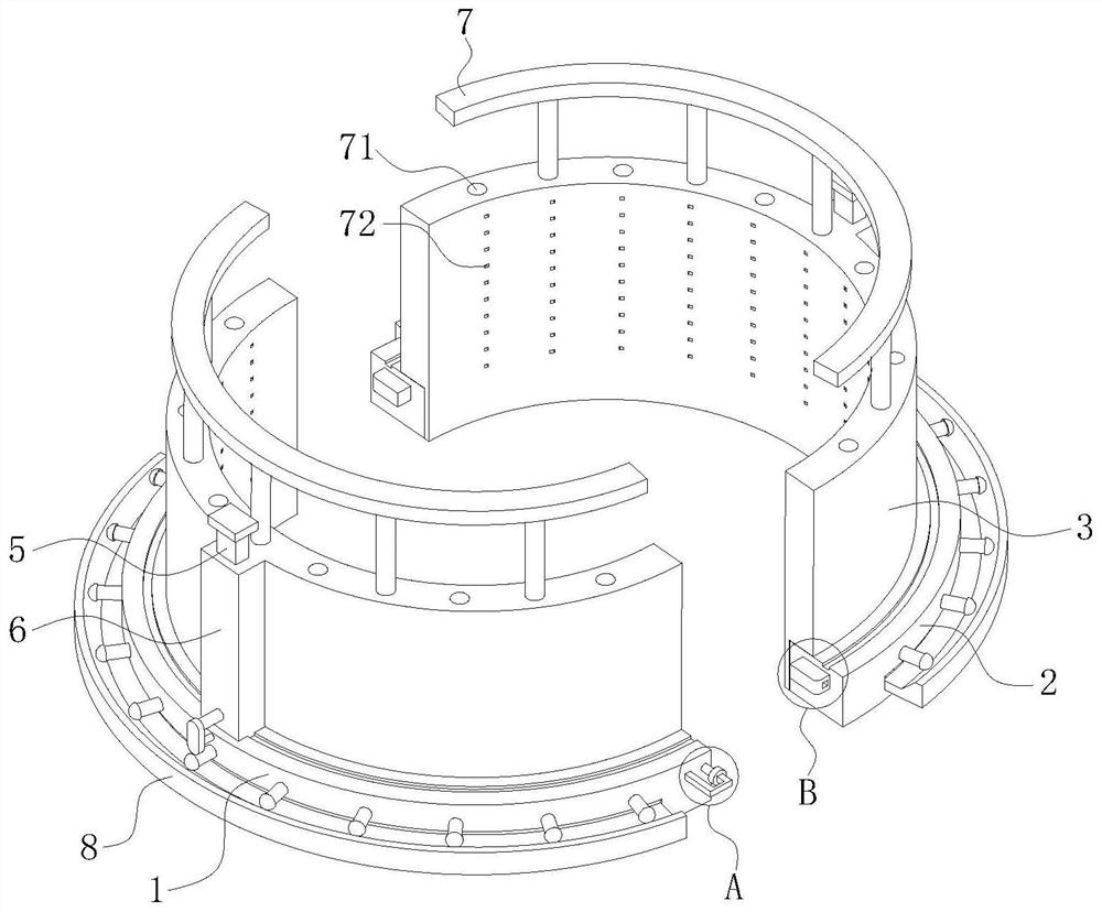
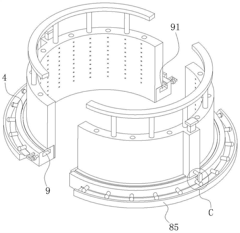
[0043] like Figure 2 to Figure 10 As shown, this embodiment provides a construction device for pouring high-strength architectural concrete columns, including a first semicircular frame 1 and a second semicircular frame 2 with the same shape and size. A semicircular arc plate 3 is rotatably mounted on the inner peripheral surfaces of the first semicircular frame 1 and the second semicircular frame 2 respectively. The two semicircular arc plates 3 coincide with the axis of the first semicircular frame 1 and the second semicircular frame 2 respectively. The surface of the semicircular arc plate 3 cooperates with the upper surfaces of the first semicircular frame 1 and the second semicircular frame 2 respectively.

[0044] The upper surface of the f...


PUM


Abstract

The invention belongs to the technical field of building construction, and particularly relates to a high-strength building concrete column pouring construction method. The high-strength building concrete column pouring construction method is completed through cooperation of a high-strength building concrete column pouring construction device and comprises the following steps of 1, butt joint fixing; 2, pouring and trowelling; 3, standing for heat dissipation; and 4, mold removal and separation. In the pouring construction process of a concrete column, heat generated in the hydration process of the concrete column is effectively dissipated, and the situation that the edge of the concrete column is prevented from being damaged in the process of dismantling a semi-arc plate, and the circumferential surface of the concrete column is scratched are avoided; the shape of the circumferential surface of the concrete column is ensured to be regular, and the pouring quality of the concrete column is improved.

Description

technical field [0001] The invention belongs to the technical field of building construction, and in particular relates to a construction method for pouring high-strength building concrete columns. Background technique [0002] Concrete columns refer to columns made of concrete materials. They are the most basic load-bearing components in various engineering structures such as houses, bridges, and hydraulic engineering. They are often used as pillars for floors, piers, foundation columns, towers, and trusses. . When constructing concrete columns, formwork needs to be installed first, and then concrete is poured into the area enclosed by the formwork, and the formwork is removed when the concrete reaches a certain strength. CN201910415601.1 discloses a semi-fabricated cast-in-place concrete column construction method, including steps: 1. Integrated horizontal assembly of reinforcement cage and steel formwork; 2. Direct anchor positioning of the integrated assembly structure ...

Claims


Application Information

Patent Timeline
Patent Type & Authority Applications(China)
IPC IPC(8): E04C3/34E04G13/02E04G17/00
CPCE04C3/34E04G13/021E04G17/002E04G17/00
Inventor 郭良红
Owner 郭良红
Why Eureka
Eureka Blog
Learn More