Wide-speed-range air inlet channel design method based on double-incidence bending shock waves

A bending shock wave and design method technology, applied in the direction of mechanical equipment, jet propulsion devices, gas turbine devices, etc., can solve the lack of wide-speed range inlet design methods, narrow the scope of inlet geometric structure, and limit the choice of reference flow field range and other issues to achieve the effect of reducing the Mach number of the throat, reducing losses and increasing thrust

Active Publication Date: 2021-07-23
XIAMEN UNIV
View PDF9 Cites 1 Cited by
  • Summary
  • Abstract
  • Description
  • Claims
  • Application Information

AI Technical Summary

Problems solved by technology

At the same time, researchers generally use the traditional characteristic line method to carry out the reverse design of the reference flow field, which is not only complicated in programming, but also poor in stability, which limits the selection range of the reference flow field, thereby reducing the geometrical structure of the inlet.
It can be seen that one of the problems currently restricting the performance of the air intake of wide-speed aircraft is the lack of a design method for wide-speed air intakes based on double-incident bending shock waves.

Method used


Image

  • Wide-speed-range air inlet channel design method based on double-incidence bending shock waves
  • Wide-speed-range air inlet channel design method based on double-incidence bending shock waves
  • Wide-speed-range air inlet channel design method based on double-incidence bending shock waves

Examples


Embodiment Construction

[0031] In order to make the technical problems, technical solutions and beneficial effects to be solved by the present invention clearer and clearer, the present invention will be further described in detail below in conjunction with the accompanying drawings and embodiments.

[0032] Such as Figure 1-7 As shown, the wide-velocity domain inlet design method based on double-incident curved shock waves includes the following steps:

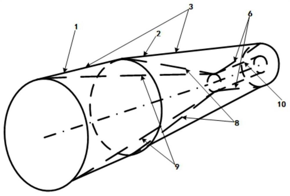
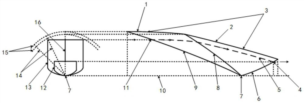
[0033] 1) Designate the reference flow field 15 of the double-incident bending shock wave according to the design requirements, the first three-dimensional bending incident shock wave 9 and the second three-dimensional bending incident shock wave 8, wherein, due to the axial symmetry of the double-incident bending shock wave reference flow field 15 In different reference planes 14, the first three-dimensional curved incident shock wave 9-shaped line has the same shape, and the second three-dimensional curved incident shock wave 8-shaped line has th...


PUM


Abstract

The invention discloses a wide-speed-range air inlet channel design method based on double-incidence bending shock waves. The method comprises the following steps of designing a double-incidence bending shock wave reference flow field based on the bending shock wave theory; designing an air inlet channel initial throat section molded line, and performing reverse flow streamline tracking in the reference flow field to obtain an initial air inlet channel compression molded surface; designing an air inlet channel isolation section outlet section, expanding an air inlet channel initial throat section in a double-S-bend form, and stretching in an equal-straight manner to obtain a three-dimensional inward-turning wide-speed-range air inlet channel isolation section; carrying out wall surface fairing and viscosity correction; taking the tail end of a first-stage compression molded surface of an air inlet channel as the rotating shaft position of a first-stage splitter plate, and taking the length of a second-stage compression molded surface as the length of the first-stage splitter plate; taking the position where the second derivative of an upper wall curve of the air inlet isolation section is zero, taking the position as the position of a second-stage splitter plate rotating shaft, and taking the length from the second-stage splitter plate rotating shaft to the air inlet channel initial throat section as the length of the second-stage splitter plate; and designing a discharge port area under the Mach number and a throat area under the Mach number. Expansion waves at the position of the rotating shaft can be eliminated; and performance requirements are met.

Description

technical field [0001] The invention relates to the field of air intakes of wide-speed range aircraft, in particular to a design method for wide-speed range air intakes based on double-incident curved shock waves. Background technique [0002] At present, wide-speed aircraft is a popular research topic in the world's aerospace powers, and it is also an important direction for future aircraft development. As the core component of the propulsion system, the air inlet is used to capture enough airflow for the engine while achieving high-efficiency compression to ensure that the entire propulsion system generates enough thrust to meet the aircraft's work in a wide speed range. According to different forms of incoming flow compression, the current hypersonic inlets mainly include: binary inlets, axisymmetric outer cone inlets, side pressure inlets and three-dimensional internal rotation inlets. types. Among them, the three-dimensional internal rotation inlet has the characteris...

Claims


Application Information

Patent Timeline
Patent Type & Authority Applications(China)
IPC IPC(8): F02C7/042F02C7/057
CPCF02C7/042F02C7/057Y02T90/00
Inventor 朱呈祥曹盛施崇广尤延铖
Owner XIAMEN UNIV
Why Eureka
Try Eureka