Strain benchmarking method of hub bearing dynamic test beds

A wheel bearing and dynamic test technology, which is applied in the field of wheel bearings, can solve the problems of varying test life results, affecting force effects, and inability to determine factors affecting life, etc.

Active Publication Date: 2021-07-23
ZHEJIANG WANXIANG PRECISION IND +1
View PDF5 Cites 0 Cited by
  • Summary
  • Abstract
  • Description
  • Claims
  • Application Information

AI Technical Summary

Problems solved by technology

With the development of automobile technology, the accuracy of wheel bearing performance test results is increasingly concerned. The traditional calibration method of calibrating the load sensor on the test bench once a year is difficult to ensure the accuracy of the test results. Because the force on the test sample is transmitted to the test sample according to the path of "loading cylinder-load sensor-loading arm-test sample", even if the accuracy of the load sensor is guaranteed, there is a gap between the load sensor and the test sample. The influence of the transmission link of the loading arm will also affect the actual force effect
Therefore, even if the two dynamic test benches ensure that the loads on the load sensors are the same, the test life results will vary widely, and the factors that affect the life cannot be determined

Method used


Image

  • Strain benchmarking method of hub bearing dynamic test beds
  • Strain benchmarking method of hub bearing dynamic test beds
  • Strain benchmarking method of hub bearing dynamic test beds

Examples


Embodiment 1

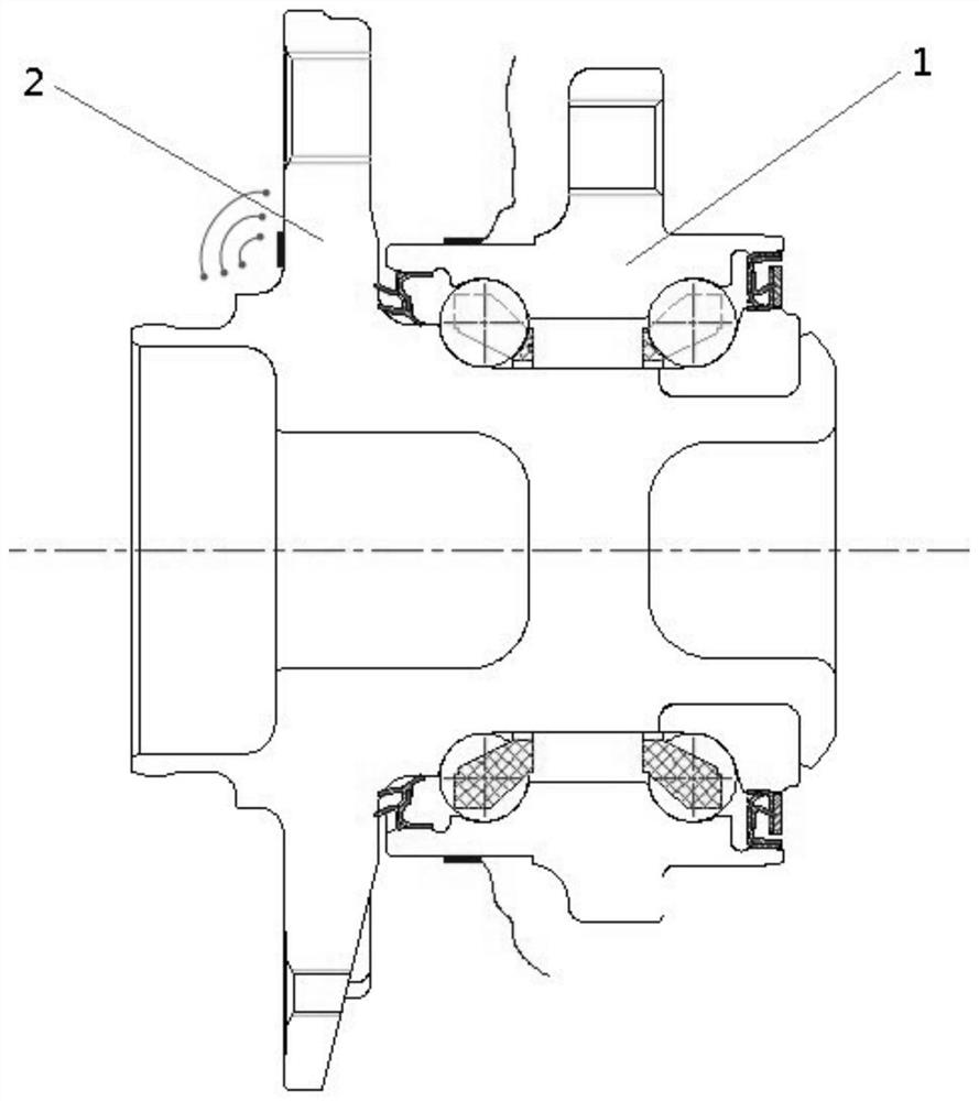
[0028] Embodiment 1: As shown in the accompanying drawings, the strain benchmarking method of the wheel hub bearing dynamic test bench mainly includes the following steps:

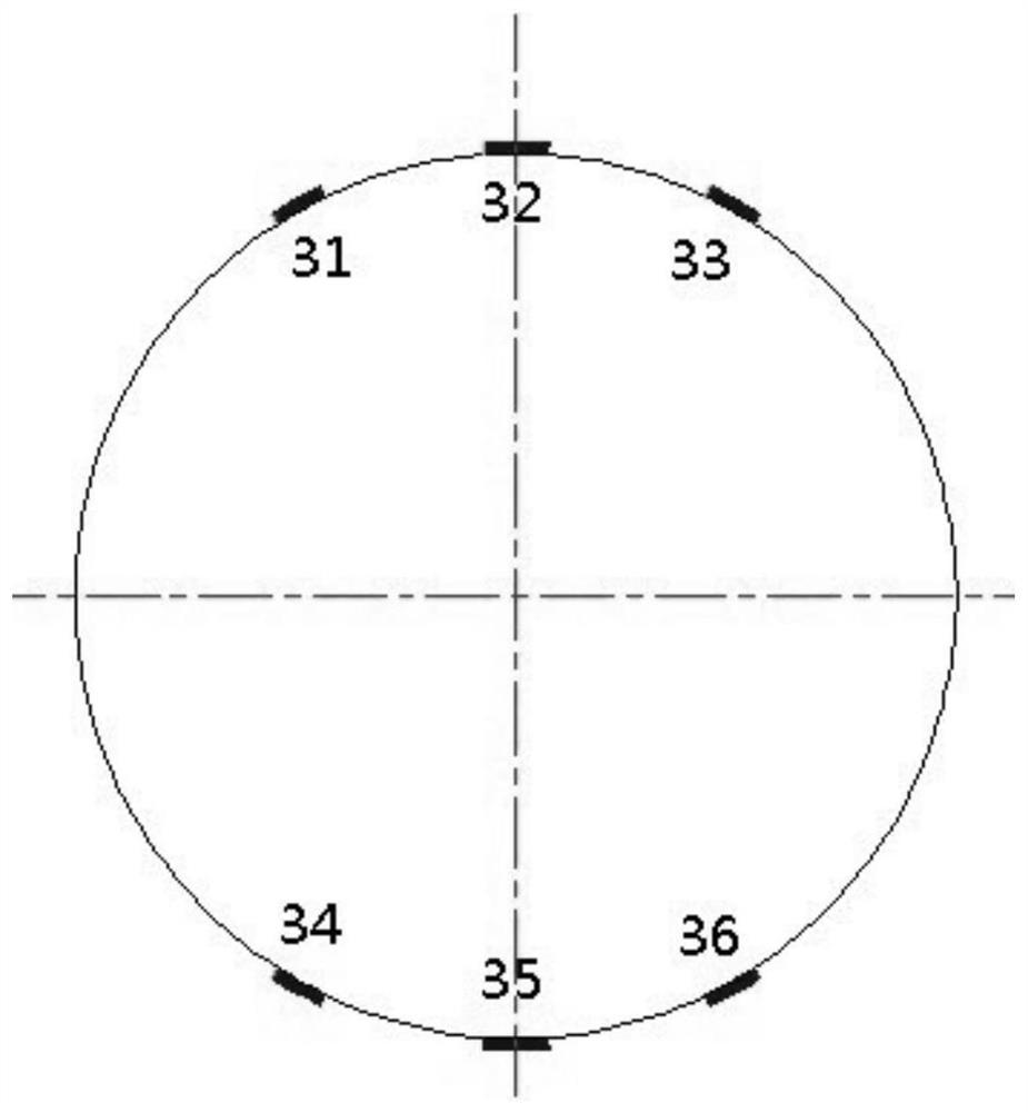
[0029] 1) Production of strain-type standard sample 5: as attached figure 1 As shown, select a hub bearing unit composed of outer ring 1 and flange 2, and perform grinding treatment on six areas of the outer surface of outer ring 1, so that the surface roughness is controlled within Ra0.8, and then use air-curing glue ( Such as 502 glue) respectively paste the strain gauge A31, strain gauge B32, strain gauge C33, strain gauge D34, strain gauge E35, and strain gauge F36 on the surface of the outer ring 1. The outer ring 1 is a non-rotating part in the work of the hub bearing. The orientation is kept in the vertical direction, and strain gauge B32 and strain gauge E35 are respectively arranged in the direction of the vertical line of the wheel, and strain gauge A31, strain gauge C33, strain gauge D34, strain...

Embodiment 2

[0045] Embodiment 2: adopt the inventive method, carry out the test of 1 standard test rig and 1 non-standard test rig respectively, choose the 6th step in 8 loading steps to carry out the analysis and evaluation of test collection data, in the 6th step condition Down:

[0046] The outer ring 1 is a non-rotating part, and the output results of the 6 strain gauges on it are shown in Table 2:

[0047] Table 2 Outer ring 1 strain output result table

[0048] Strain gauge number Standard test bench strain (μeps) Non-standard test bench strain (μeps) Relative error(%) evaluate 31 193 202 4.3 OK 32 265 269 1.5 OK 33 186 194 4.4 OK 34 -123 -120 -3.2 OK 35 -242 -239 -1.2 OK 36 -133 -129 -3.0 OK

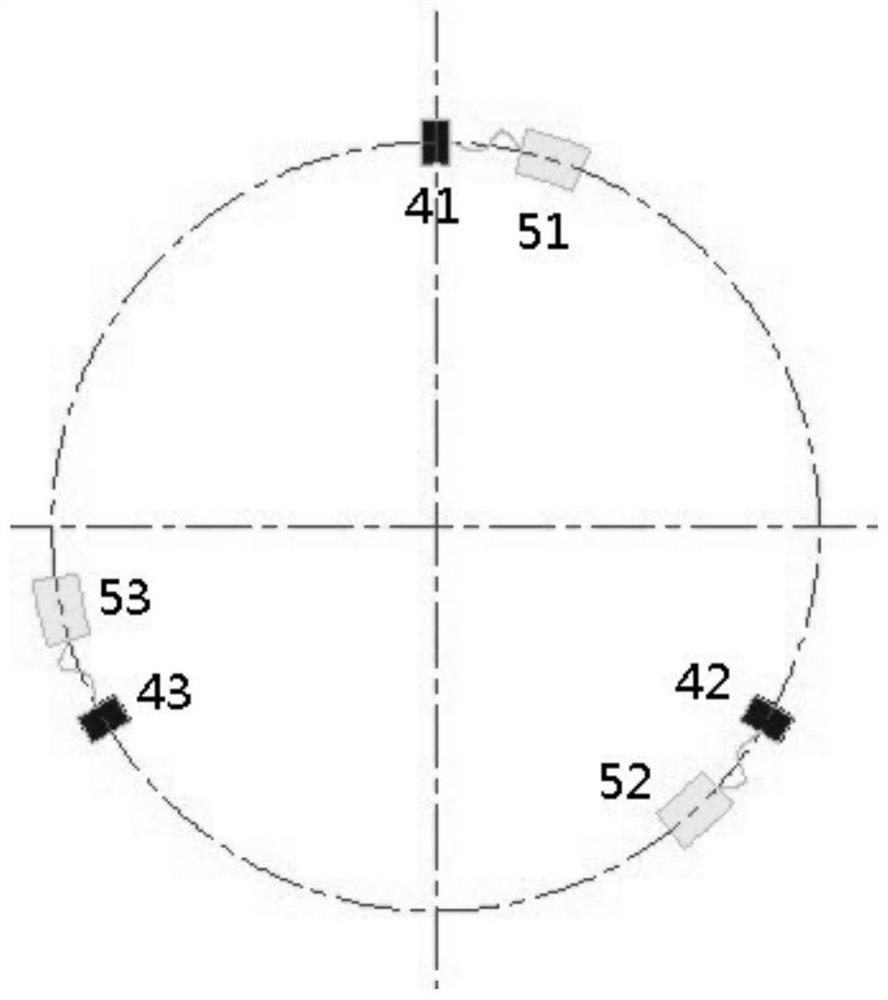
[0049] Flange 2 is a rotating part, and the output results of the three strain gauges on it are all sinusoidal, as shown in the attached Figure 5 The signal output result graph of the strain gauge G41 is shown.

...


PUM


Abstract

The invention discloses a strain benchmarking method of hub bearing dynamic test beds. The strain benchmarking method mainly comprises the following steps of: manufacturing a strain type standard sample; matching a test tool and formulating a load spectrum; implementing a test; and analyzing and evaluating data. The method is used for comparing and evaluating the strain difference of two or more test beds under the same loading load; a terminal sample piece strain measurement and evaluation mode is directly adopted; and the problem of transmission from a load sensor to a loading arm and a connecting fastener is fully considered, so that the influence degree of different test beds on the dynamic life test of a product is evaluated, and the reasons of the influence can be deeply analyzed, and an effective analysis means is provided for the dynamic life difference of two or more test beds.

Description

technical field [0001] The invention relates to the field of hub bearings, in particular to a strain calibration method of a dynamic test bench for hub bearings. Background technique [0002] The dynamic test bench is a test system for simulating hub bearings under actual driving and loading conditions. Strain is a description of the deformation caused by a material under load. With the development of automobile technology, the accuracy of wheel bearing performance test results is increasingly concerned. The traditional calibration method of calibrating the load sensor on the test bench once a year is difficult to ensure the accuracy of the test results. Because the force on the test sample is transmitted to the test sample according to the path of "loading cylinder-load sensor-loading arm-test sample", even if the accuracy of the load sensor is guaranteed, there is a gap between the load sensor and the test sample. The influence of the transmission link of the loading arm...

Claims


Application Information

Patent Timeline
Patent Type & Authority Applications(China)
IPC IPC(8): G01M13/04G01B21/32
CPCG01M13/04G01B21/32
Inventor 黄德杰周旭姜金东王青娣
Owner ZHEJIANG WANXIANG PRECISION IND
Why Eureka
Try Eureka